
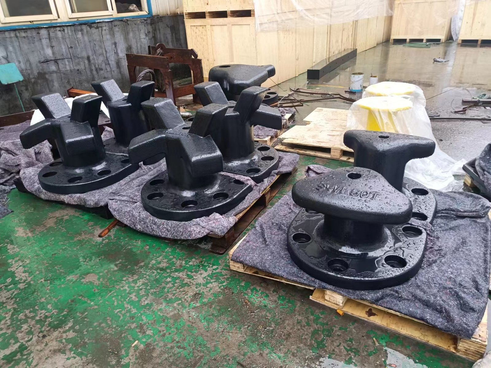
Mooring Bollards for Ports, Quays and Jetties
JettyGuard supplies shore-side mooring bollard configurations for project-specific berth load cases, interfaces and documentation requirements.
The quotation route begins with the application, type, required rating, structure condition and verification scope. Before those inputs are settled, it is worth separating shore-side mooring equipment from the shipboard and tug terminology that shares the same words.
What is a shore-side mooring bollard?
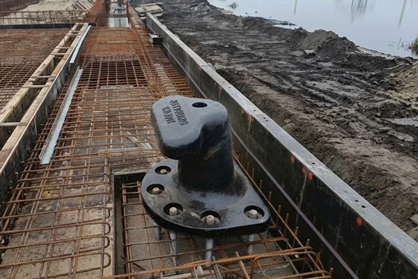
A shore-side mooring bollard is a fixed fitting installed on a quay, jetty, wharf, dolphin or similar berth structure to receive vessel mooring lines and transfer their loads into the supporting structure. Two adjacent terms lead to a different specification path:
Shipboard bollards
A shipboard welded bollard or bitt is installed on a vessel and follows a different equipment route. ISO 13795 covers welded steel bollards for sea-going vessels.
Tug bollard pull
Tug bollard pull describes a tug's pulling force. It is not the working-load rating of a shore-side mooring bollard.
Where are mooring bollards used?
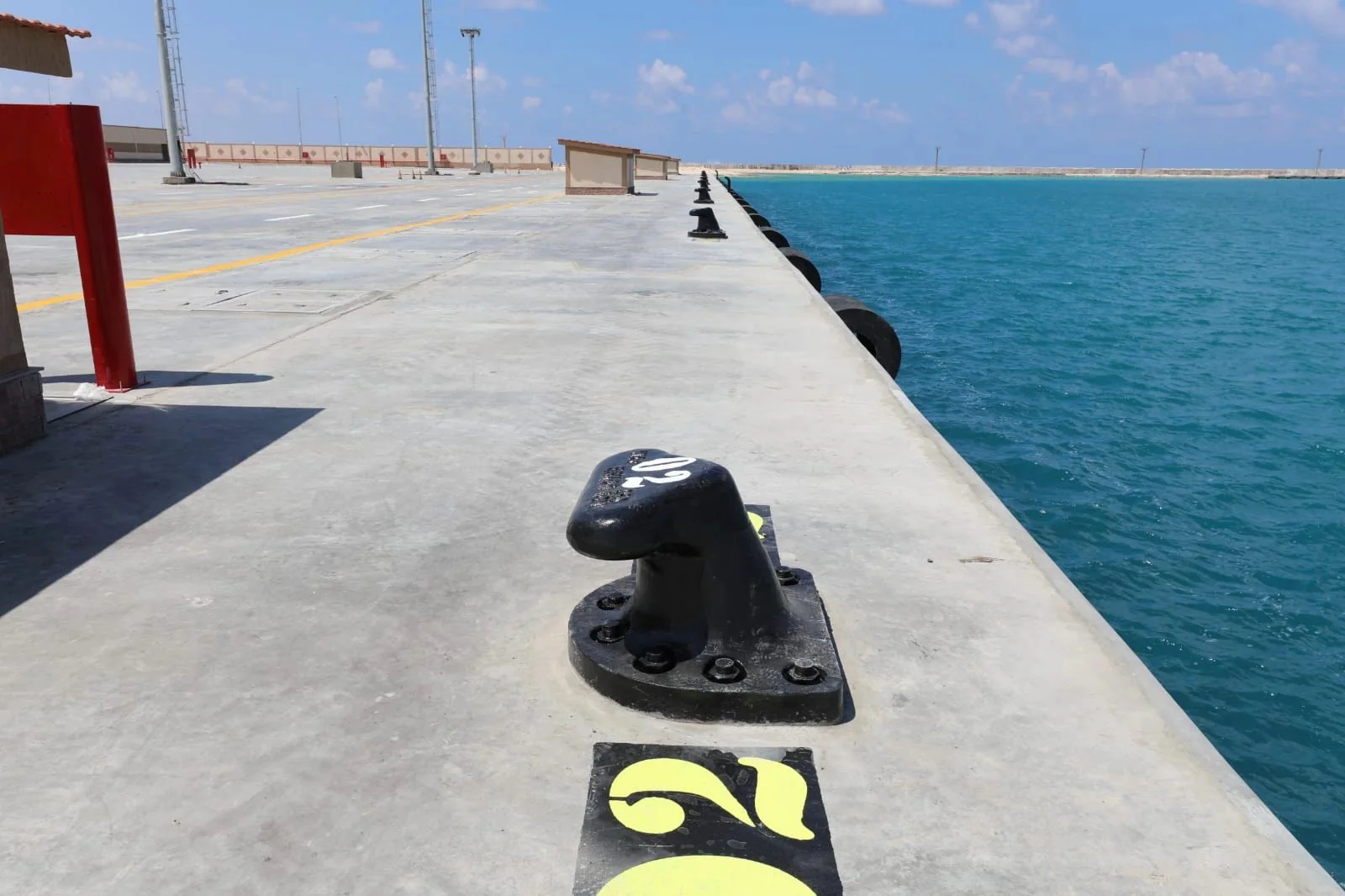
Shore-side mooring bollards are specified on the fixed marine structures listed below. The application affects the berth load case, line geometry, fitting location and structural interface. It does not create a universal type or capacity recommendation.
Ports and quays
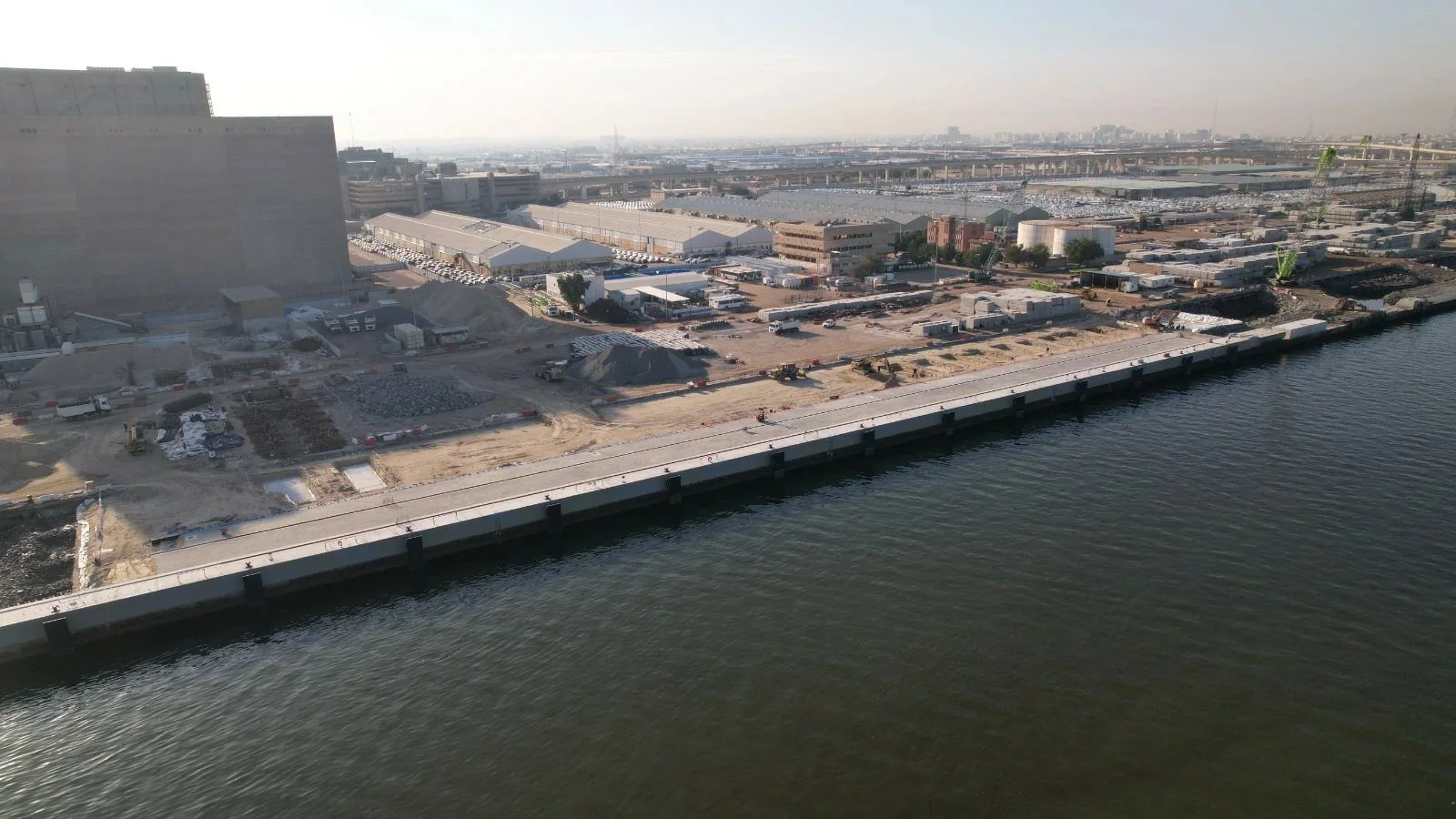
Continuous quay walls with regularly spaced bollards selected against the design vessels and mooring analysis.
Jetties and piled berths
Bollards mounted on capping beams or dedicated blocks, where line angles and uplift affect the interface.
Mooring dolphins
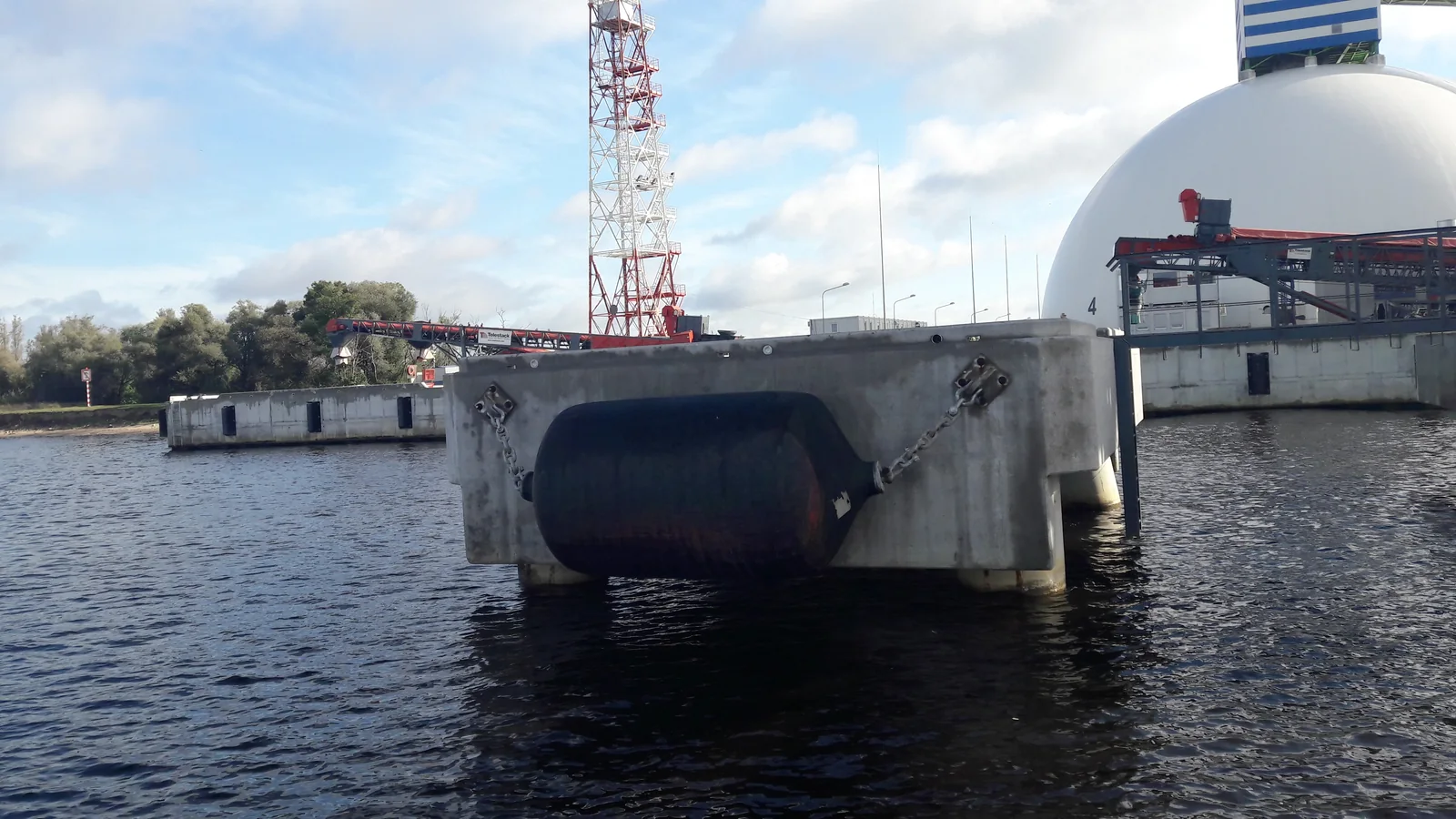
Isolated structures where a bollard receives concentrated mooring-line loads while fenders carry berthing reactions on the breasting structure.
LNG, oil and bulk terminals
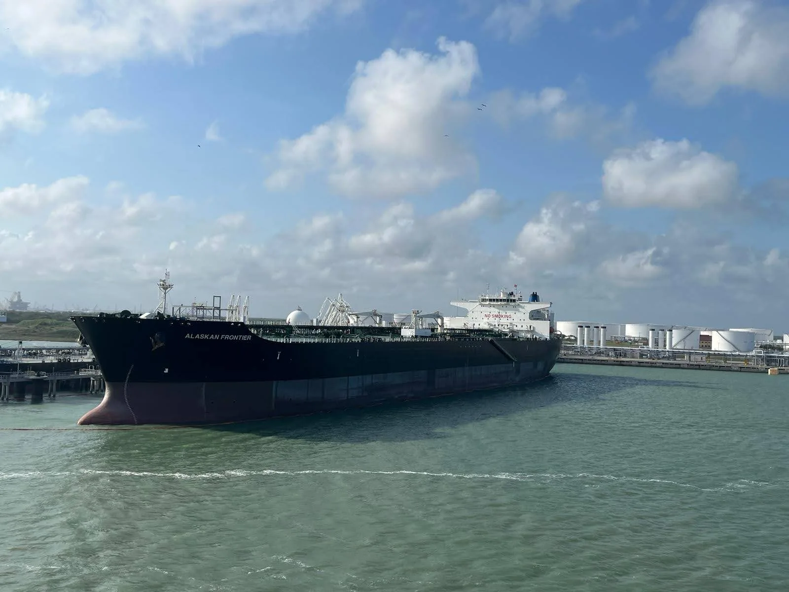
Berths where mooring layout, quick-release hooks and bollards are engineered together against the terminal mooring analysis.
Marinas, canals and locks
Lighter berths, pontoons, banks and lock walls where single-bitt bollards or cleats may form part of the mooring arrangement.
Bollard types
Choose a shore-side mooring bollard type
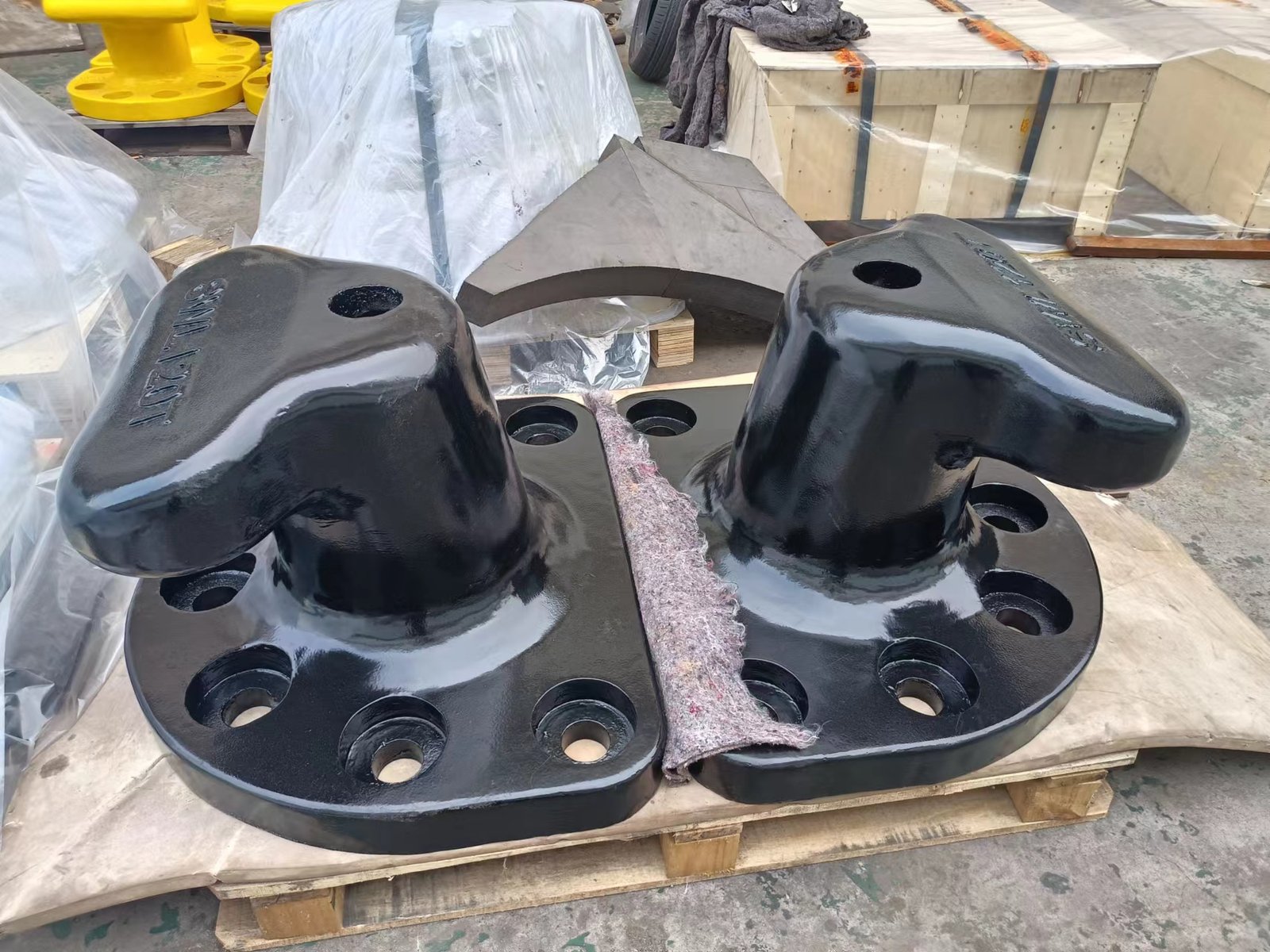
The available range covers the following forms, with custom bollard head and base configurations available for project-specific requirements. Shape is an orientation step; the final form and rating remain subject to the project load case and interface.
Specify the bollard around the berth load case
Confirm the following inputs before a rating is requested:
- 01
Rating basis
Confirm the required SWL or governing design load together with the mooring-analysis basis.
- 02
Line geometry
Confirm horizontal and vertical line angles and the number of lines led to each fitting.
- 03
Water-level change
Account for tidal range or vessel draft change.
- 04
Location and interface
Confirm the bollard location and the interface with a new or existing structure.
- 05
Capacity and terminology
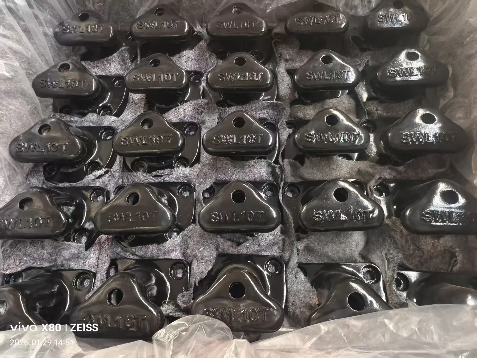
Mooring bollards can be supplied with SWL up to 300 tonnes, subject to the project load case, form, material and interface. SWL (safe working load) and WLL (working load limit) describe the rated capacity for normal service conditions; MBL (minimum breaking load) represents the load at which the fitting would fail. Project documents may use different terms, so the governing terminology and acceptance basis should be confirmed. BS 6349-4:2026 and PIANC WG 186 provide relevant context for mooring loads, assessment and line geometry.
Match material, coating and anchor approach to the project
Existing or aged concrete, insufficient thickness, reinforcement conflicts and unverified concrete strength require project-specific verification and engineering.
| Route | Available options | Project-specific confirmation |
|---|---|---|
| Material | ZG230-450 cast steel (yield strength at least 230 MPa, tensile strength at least 450 MPa, elongation at least 22%) and QT450-10 ductile iron (yield strength at least 310 MPa, tensile strength 450 MPa, elongation at least 10%) are the primary routes. Other cast-steel and ductile-iron grades may be configured for a project. | The grade is selected against the project specification. |
| Coating | Where applicable, blast preparation is Sa 2½ and the marine multi-coat system has a total DFT above 320 μm, selected to match the approved project coating specification and ISO 12944 C5-M exposure requirement. | The system is selected against the approved project coating specification. |
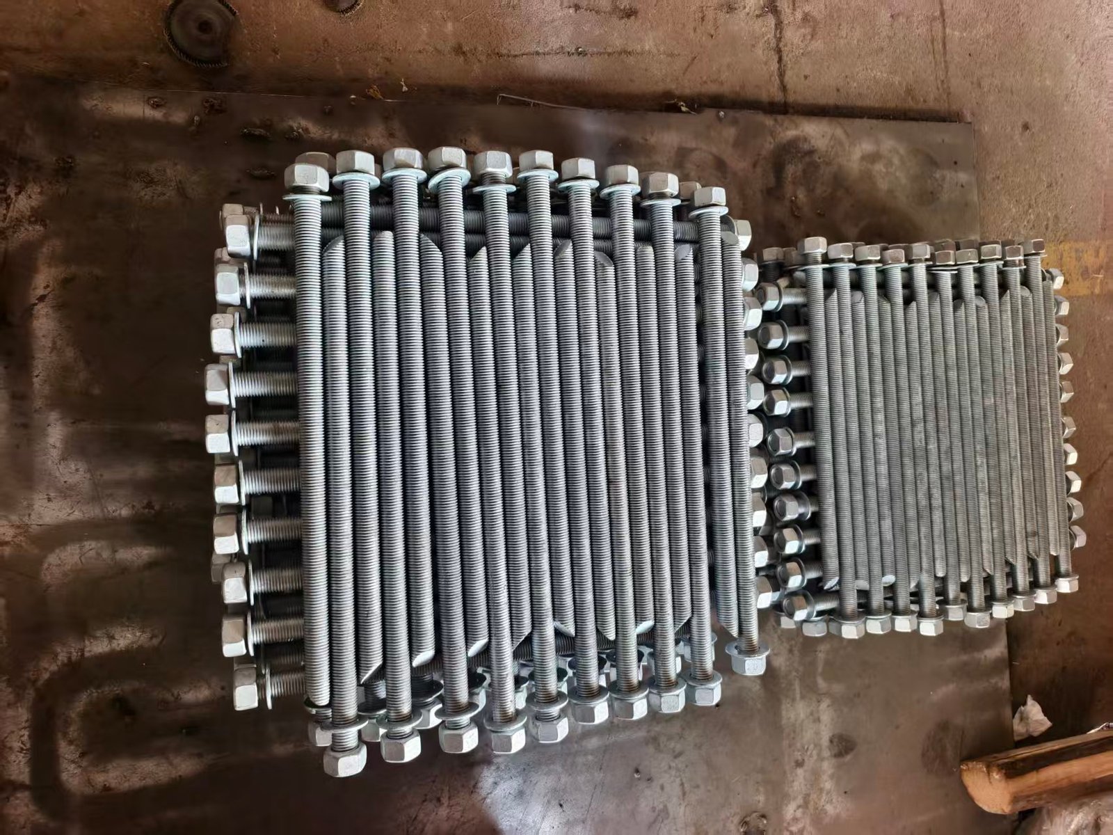
| Anchoring | Cast-in anchors, fully threaded post-installed anchor rods and cast-in socket anchors. | The appropriate route is project-specific. |
Establish the design basis before procurement
Published guidance frames the assessment while project-specific documents control the final design basis.
- 01
BS 6349-4:2026
BS 6349-4:2026 is the current BSI code of practice for design of fendering and mooring systems and includes mooring devices and layouts, including bollards.
- 02
PIANC MarCom WG 186
Published in January 2025, it addresses mooring of large ships at quay walls, including safe working load of future bollards and the inputs used in a mooring assessment.
- 03
Project-controlled basis
The project specification, berth mooring analysis and structural design remain controlling. Citing a publication is not product certification or a universal design answer.
Define inspection, testing and documentation requirements
State the required record and inspection scope in the procurement requirement:

Supply documentation
Material certificates, dimensional inspection records, coating-DFT records, ITPs and drawings can be included in the supply documentation package.
Pull testing
Pull testing is an optional paid project activity and should be specified before quotation. Where the project verification scope requires it, BS 6349-4:2026 describes verification of a new mooring fitting's WLL by load testing to at least 130% of declared WLL; MBL verification by pull testing is at least 240% of declared WLL or 80% of yield, whichever is higher. The final scope follows the contract and project requirement.
Third-party inspection
Third-party inspection is an optional paid project activity. Its witness points and reporting scope should be stated in the project requirement.
Delivery references
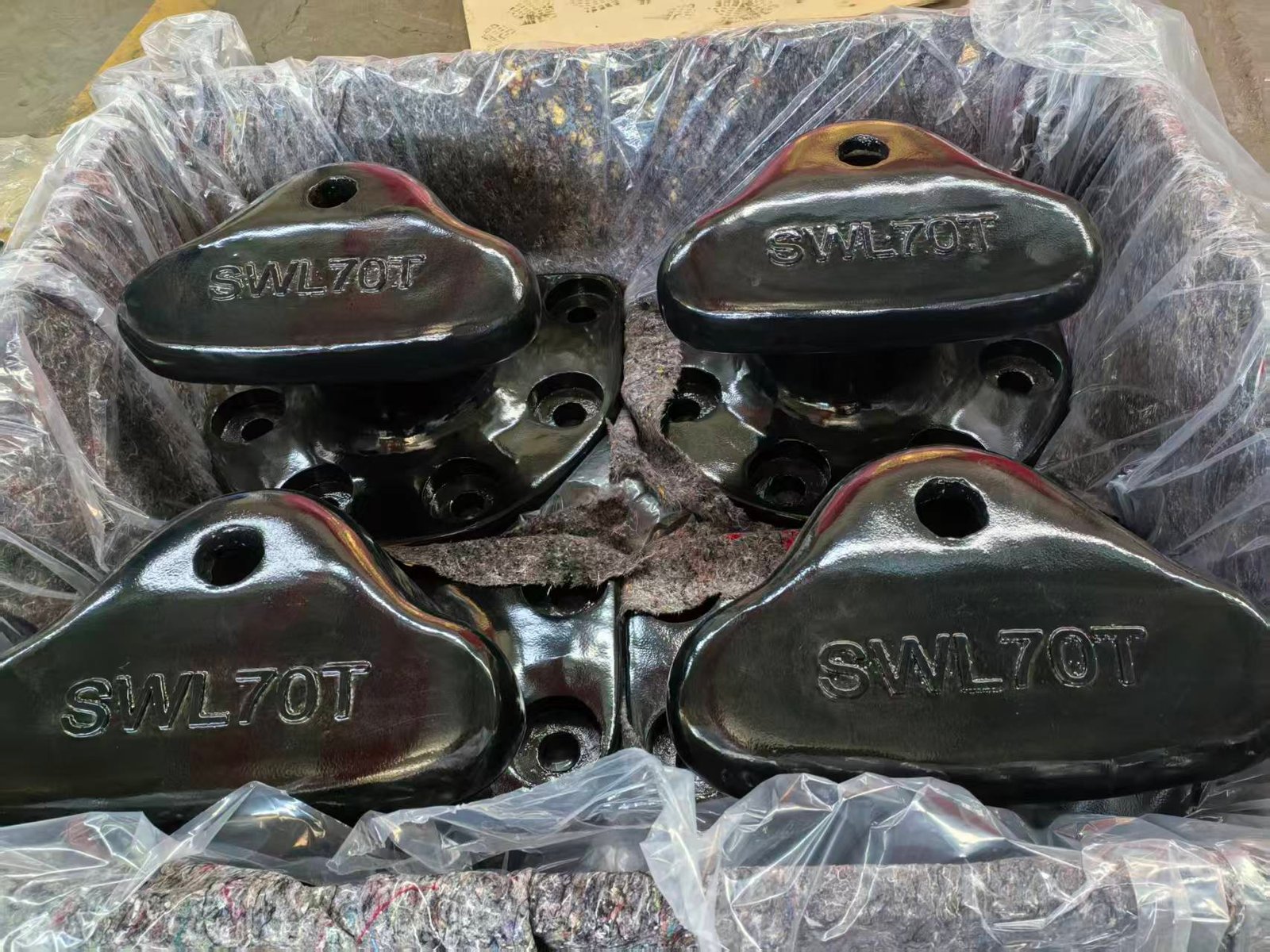
Representative mooring bollard deliveries
Select a delivery reference to view the supplied bollard type, quantity and specified capacity.
Request a mooring bollard quotation
DDP delivery can be offered subject to the destination and project scope.