
Selection and Interface Engineering
The calculation, the arrangement and the interface details are handled by the same team that supplies the hardware, so drawings, supply and site reality stay aligned.
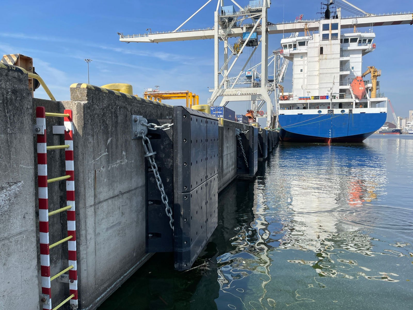
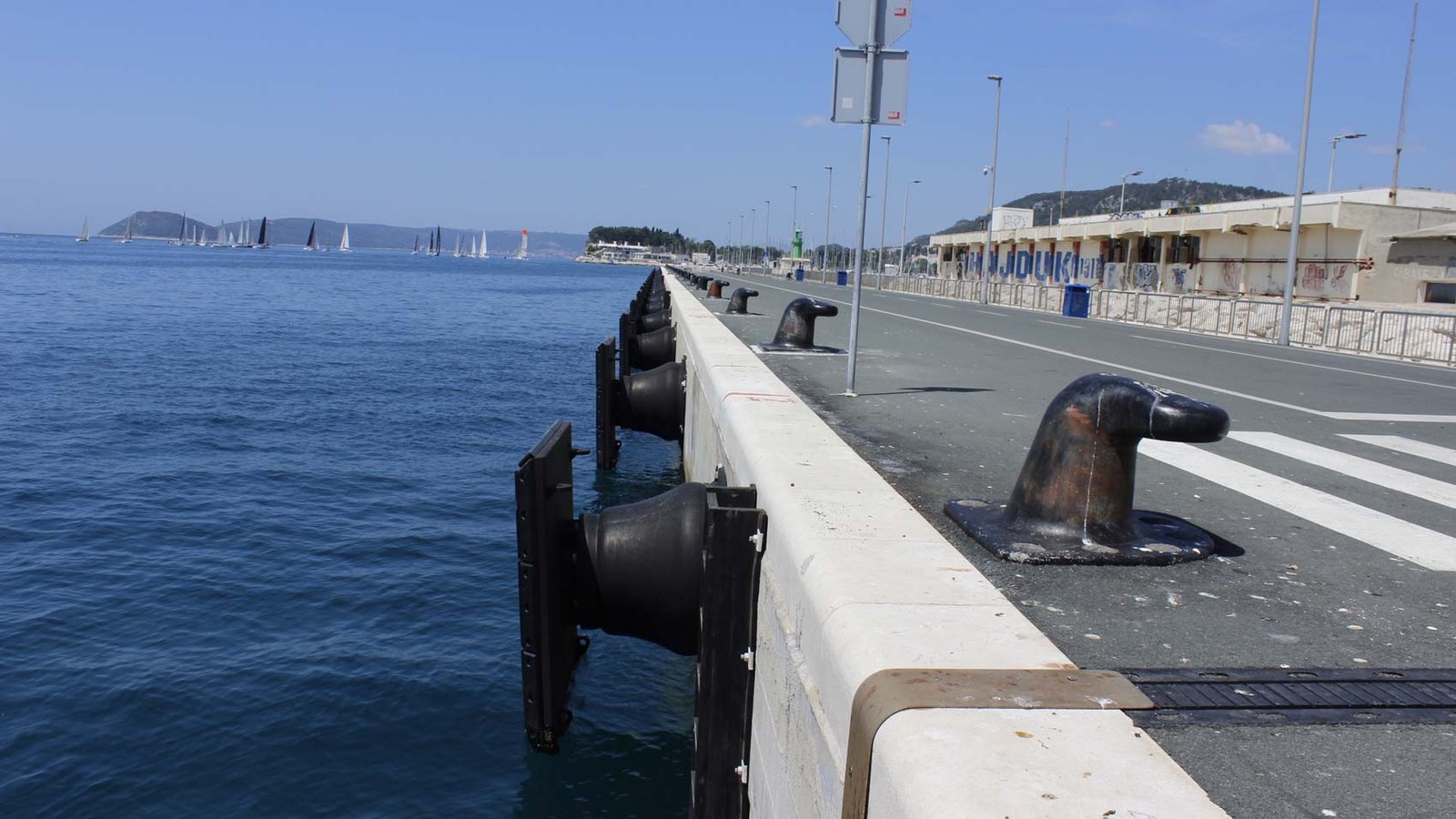
Molded rubber fender systems are configured for fixed quays, jetties, docks and piers.
Type, size, deflection series and arrangement follow the vessel, berth, geometry and acceptance inputs for the project rather than a catalogue default.
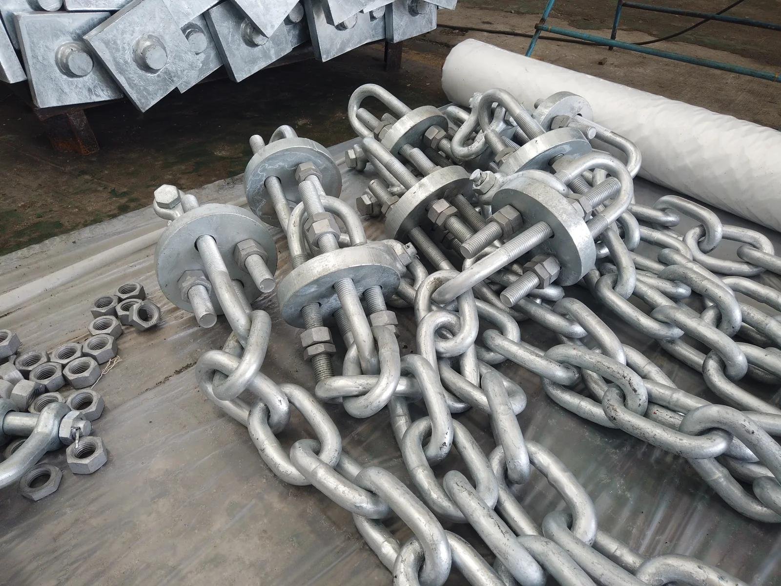
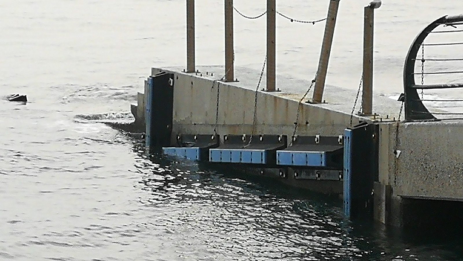
A molded rubber fender system protects a quay, jetty, dock or pier and the vessels that use it. The supplied scope is the complete assembly: the molded rubber element, the steel frontal panel, the UHMW-PE facing pads and the chains, anchors and fixings that hold it to the structure. JettyGuard engineers the selection, specifies the steel panel system, integrates the assembly and supplies the molded elements against the approved drawing set.
Three adjacent conditions are served by different systems:
Each type solves a different mix of energy, reaction force, hull pressure, installation depth and maintenance access. Type notes narrow the shortlist; the rated series and design deflection come from the project calculation.
Catalogue ranges show the nominal envelope each type reaches.
| Fender type | Catalogue series | Nominal range | Typical use in an arrangement |
|---|---|---|---|
| Cone | JCO | H 500–1800 mm | High-energy berths with large frontal panels |
| Cell | JSC | H 400–3000 mm | Wide-panel, large-berth and heavy jetty duty |
| Arch | JSA | H 150–1000 mm | Compact berths, lock walls and workboat quays |
| Unit element | JME | H 300–1600 mm | Combined element groups tuned to a target performance |
| Cylindrical | JCY | OD 150–2000 mm | Corners, piles and berths with varied vessel sizes |
Catalogue performance data carries a ±10% tolerance, and rated energy and reaction change with deflection series, temperature, berthing angle and compression speed. Final sizes come from the project selection calculation and the released datasheet.
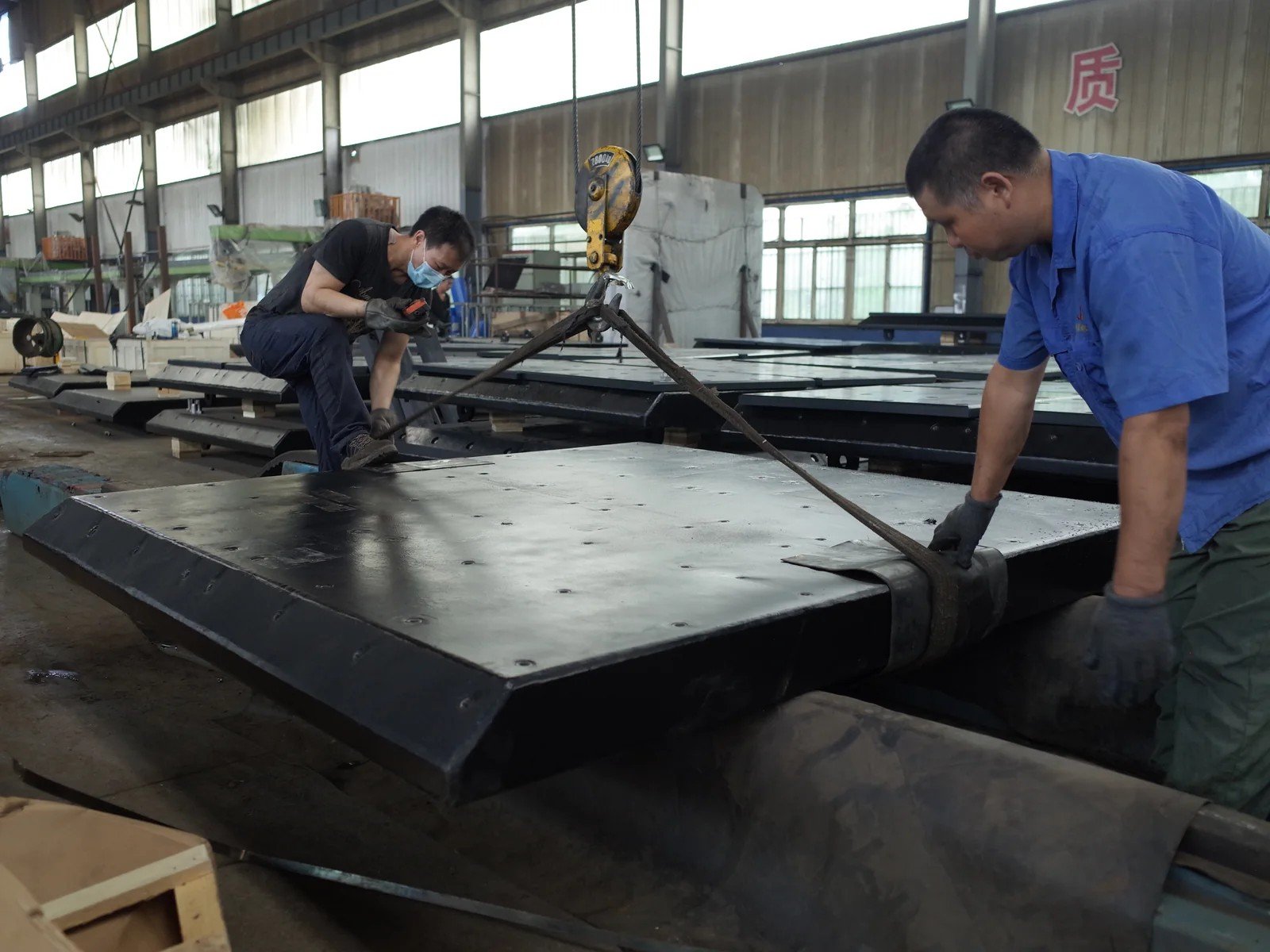
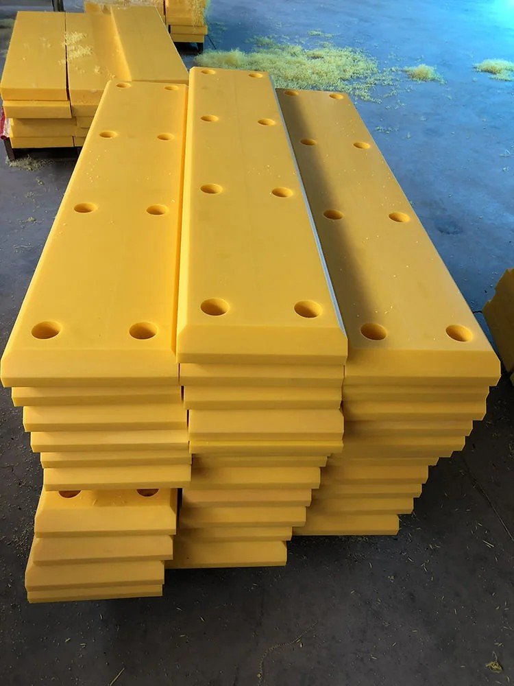
The rubber element is one of four component groups supplied and engineered together:
The energy-absorbing body (Cone, Cell, Arch, Unit Element or cylindrical), sized to the design energy and the reaction limit, produced under JettyGuard quality control to the released project specification.
Engineered around the panel loads, bending, deflection and contact area, and supplied with site-specified corrosion protection.
Low-friction pads that reduce shear transmitted into the element and protect both hull and panel plate. Pad thickness, stud pattern and replacement access are fixed on the arrangement drawing.
Weight, shear and tension chains with brackets, shackles and tensioners, plus anchor bolts or cast-in assemblies matched to the structure and to what the civil contractor can install.
The four groups are coupled, so they are verified as one arrangement:
The panel decides how the element's reaction is presented to the hull, so a change to either one moves the hull pressure result and both are fixed in the same step rather than sequentially.
The facing sets the friction coefficient that determines how much shear reaches the element and the chains.
The chain geometry controls panel travel and hang-off across the tidal range.
Change any one of them and the others need rechecking.
The sequence is fixed: establish the design case and calculate berthing energy, then shortlist a type, then select size and deflection series inside the reaction and hull pressure limits, then verify the arrangement, interfaces and records.
Four input groups define the case. Where any of them is incomplete, the selection cannot be confirmed until the missing input is supplied.
| Input | Why it matters |
|---|---|
| Vessel mix and hull geometry — vessel types, displacement and DWT range, length, beam, laden and ballast draft, freeboard, bow flare or parallel body | The largest vessel usually sets the energy; the smallest often sets the geometry and the contact position |
| Berthing conditions — approach velocity, berthing angle, tug assistance, wind, current and wave exposure, continuous mooring or short calls | These set the energy input and the angular and shear demand on the element |
| Water levels and berth geometry — deck level, high and low water levels, structure type, pile or beam spacing, available installation face, obstructions limiting fender height or panel travel | These decide whether a candidate arrangement physically fits and stays in contact across the tidal range |
| Project acceptance criteria — allowable reaction force, maximum hull pressure, design and inspection standards named in the specification, coating requirements, documents expected at approval | These are the limits the calculation must satisfy and the basis on which your consultant approves |
Berthing energy is the demand; the allowable reaction force on the structure and the maximum hull pressure on the vessel are the limits. The selected type, size and deflection series has to satisfy all three at the design deflection.
It follows from the vessel data and berthing conditions, and it is the demand the system must absorb.
The absorbed energy must meet that demand at the design deflection.
The reaction generated at that deflection must stay within the limit the structure allows.
The same reaction spread over the effective contact area of the panel gives hull pressure, which makes panel dimensions and facing layout part of this check rather than a later detail.
A lower-reaction deflection series, a different type, a larger panel or grouped elements each change the result, and the calculation confirms which combination satisfies all limits at once.
A selection that satisfies energy, reaction and hull pressure still has to work as an installed assembly and be documented to the contract.
| Verification item | What is checked or supplied |
|---|---|
| Water levels and contact geometry | That the fender stays in effective contact with the hull between high and low water for the full vessel range, at the design berthing angle |
| Panel travel and clearances | That the panel can deflect fully without fouling the structure, adjacent fenders, services or obstructions |
| Chains, anchors and fixings | Chain geometry, bracket positions, anchor or cast-in details matched to the structure and to installable tolerances |
| Arrangement drawings | Fender arrangement, panel and facing layout, chain geometry and anchor or bolt details, issued for review and updated to approved status |
| Selection calculation | Berthing energy, selected type and size, deflection, reaction force and hull pressure check, presented so your consultant can verify the basis |
| Material and performance records | Material and performance test reports for the supplied elements, plus steel, welding and coating records for the panel system |
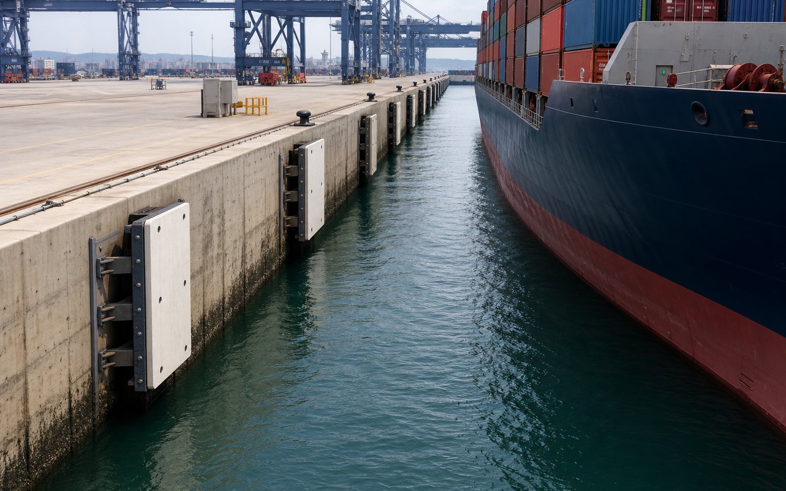
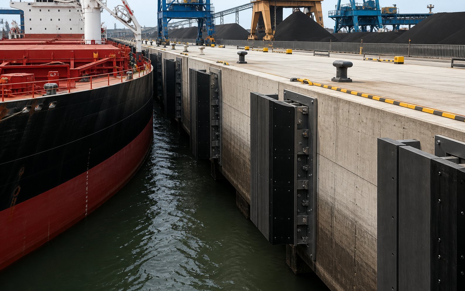
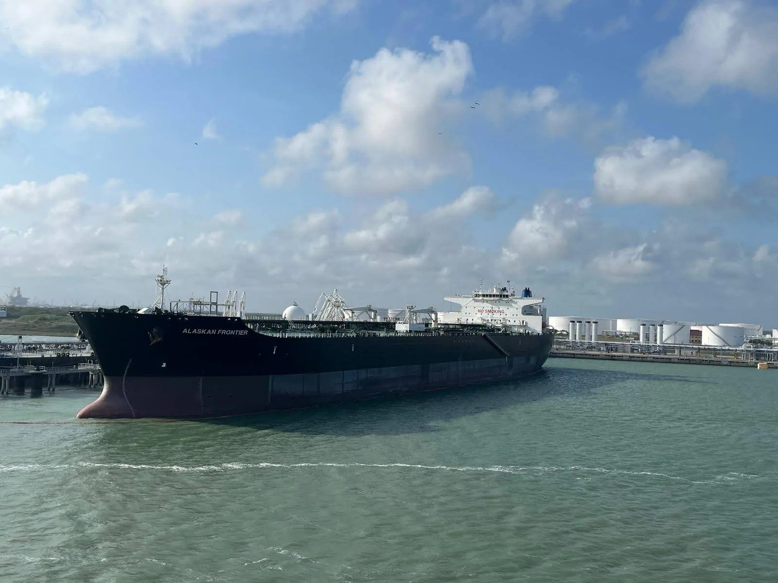
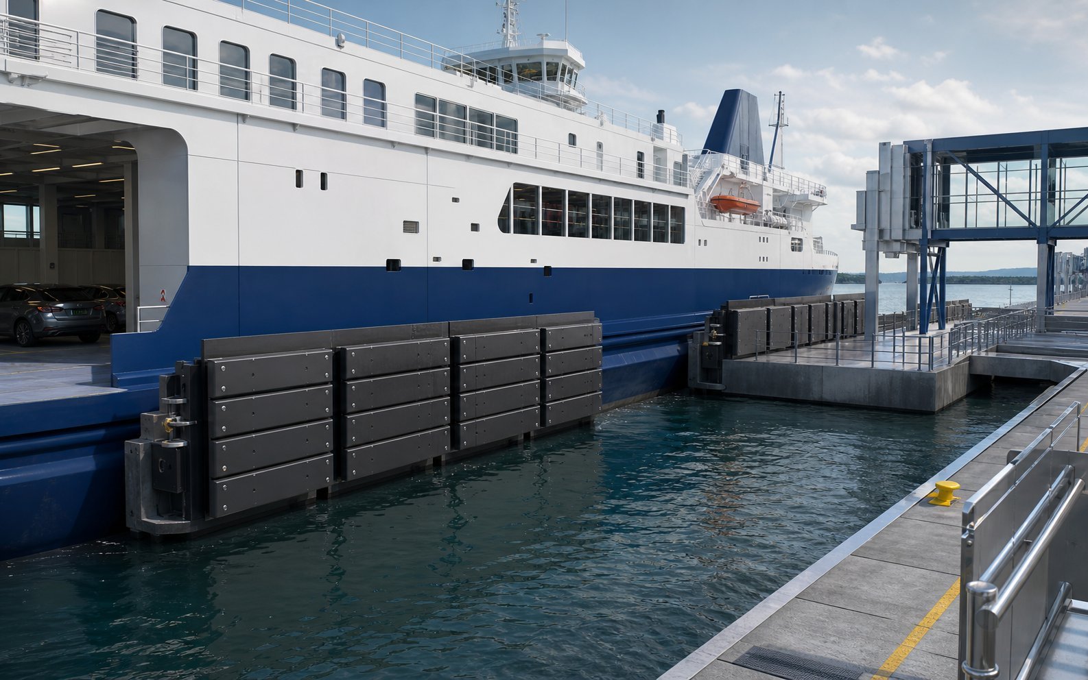
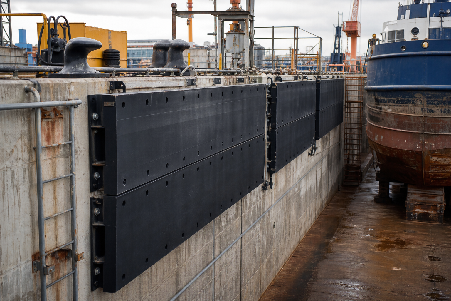
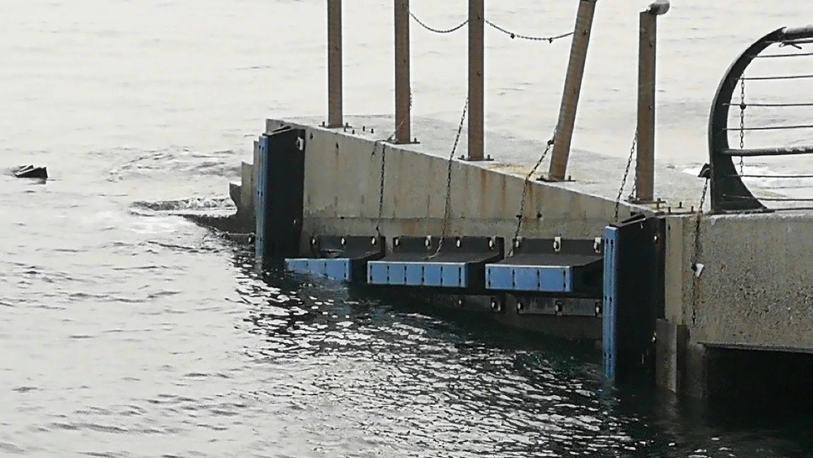
Berth type changes vessel contact, reaction limits, access, replacement needs and the arrangement that has to be verified.
Long continuous quay lines with a wide vessel range; panel size and fender spacing must protect flared bows without overloading smaller feeder hulls.
Heavy displacement, frequent calls and abrasive conditions; element robustness and simple facing replacement matter alongside rated energy.
Strict hull pressure limits and low reaction targets on breasting dolphins, commonly large panels on Cone or Cell elements; energy, reaction, hull pressure and dolphin geometry are checked together. Where a floating alternative is still under consideration for a gas berth, see the pneumatic fender versus cone fender comparison for LNG berths.
pneumatic fender versus cone fender comparison for LNG berthsHigh call frequency, tight approach angles and side-thruster wash; fast element replacement and durable facings keep the berth in service.
Fit-out quays, repair berths and dock entrances handling mixed hull forms, where geometry and mounting flexibility often weigh more heavily than peak energy.
Lock walls, pier corners, dolphins and pontoons with limited installation depth, frequently suiting Arch or cylindrical elements mounted directly to the face.
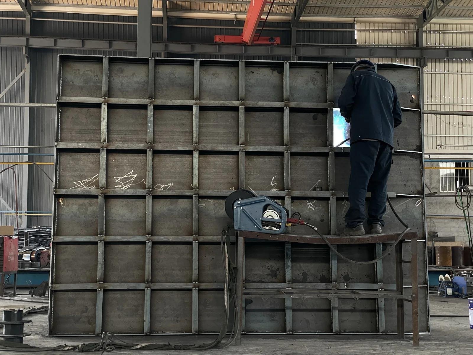
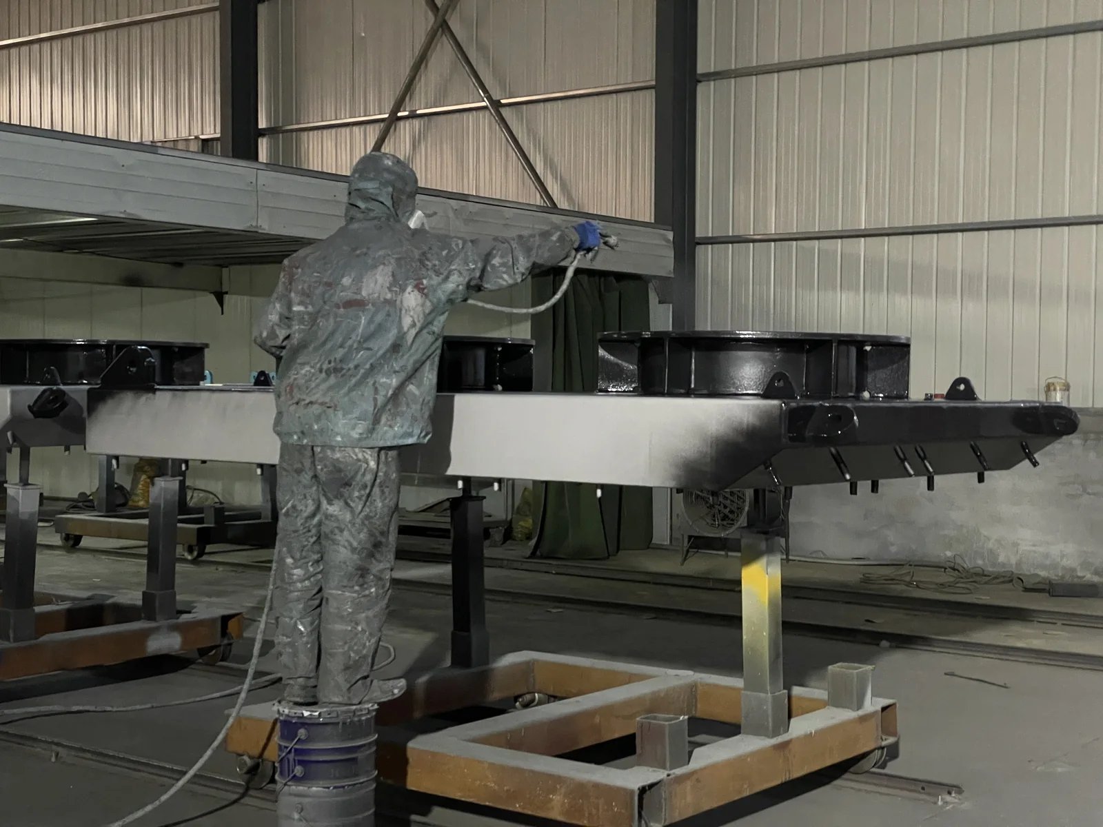
The calculation, the arrangement and the interface details are handled by the same team that supplies the hardware, so drawings, supply and site reality stay aligned.
The steel panel system, element, facing and hardware are specified and supplied as one engineered scope, so fit-up questions have a single owner.
Molded elements are produced under JettyGuard quality control to the released project specification, with dimensional and performance checks recorded against the approved drawings.
Parts are marked and matched against the approved arrangement and shipped to the agreed Incoterm with the contracted marking and packing, together with installation drawings including bolt and chain data.
Send what you have. Partial data is enough to start.
Types, displacement or DWT range, length, beam, laden and ballast draft, freeboard
Approach velocity, berthing angle, tug assistance, wind, current and wave exposure
Berth type, deck level, high and low water levels, pile or beam spacing, available installation face
Allowable reaction force on the structure and maximum permitted hull pressure
Elements only or a complete system with panels, facings, chains and anchors; number of fender positions, spares and required delivery window
Specification extracts, berth drawings, existing fender details for replacement work, destination port, delivery term, and the documentation or inspection your contract requires
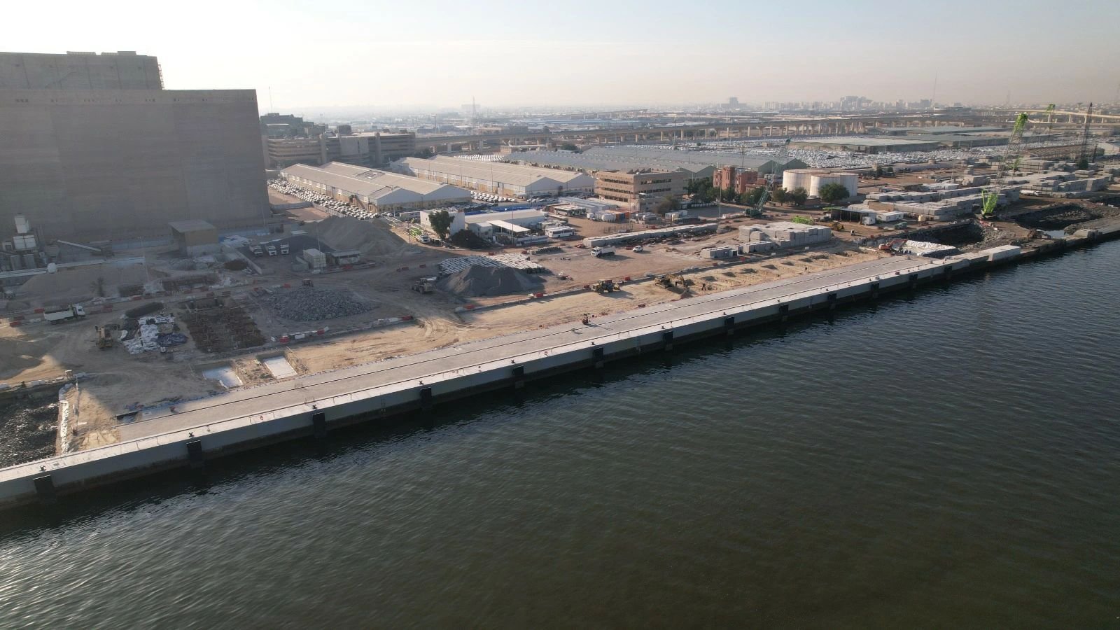
No. The approved arrangement decides. High-energy Cone, Cell and Unit Element arrangements normally distribute load through a steel frontal panel, while Arch and fixed cylindrical elements are often mounted directly to the berth face or fitted with a facing plate instead. Contact geometry, hull pressure and the mounting surface determine which of the three configurations is approved for a given position.
Only when they are written into the contract. Where the specification calls for them, the inspection body, the hold points, the sample rate and the reporting format are agreed per project before production, so the scope is explicit rather than assumed.
Installation drawings with bolt and chain data are part of the supplied delivery evidence. Attendance on site is not: on-site guidance during installation is a separately scoped and quoted service, agreed with the berth programme in mind.
Send the vessel range, berthing conditions and structure details you have today. Our engineers work from that data, tell you which inputs are still missing, and return the selection, an arrangement proposal and a quotation once the case is complete.
