
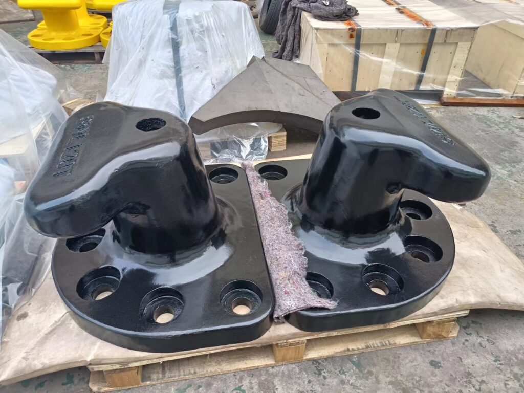
A retrofit needs evidence before it needs a design. When an existing concrete dock must accommodate a replacement or additional bollard, the existing fitting, load duty and foundation are often not known.
Request the existing bollard photographs, original drawings, inspection records, type, SWL and bolt-interface status before any design begins. Where the intended SWL does not increase, the original bollard SWL can serve as a planning reference. Where the intended SWL may increase, obtain the owner’s engineering company’s mooring analysis or the calculation inputs before proposing a higher capacity.
Retrofitting a mooring bollard on an existing concrete dock is not a standard anchorage project. Unknown reinforcement, foundation depth and load history must be separated into what can be verified, calculated and approved before a concrete, anchor or bollard decision proceeds.
What Must Be Verified Before a Bollard Retrofit Is Designed?
A responsible project cannot begin with an assumed solution. When a supplier is asked to design or price a retrofit, they need the inputs that establish the existing condition, the intended duty and the engineering boundary.
Collect existing bollard photographs, original technical drawings, inspection or maintenance reports, the bollard type and marked SWL, and clarify whether the retrofit will match the original bolt pattern or require a new anchorage arrangement. If the project intends to raise the required SWL, provide the owner’s engineering company’s mooring analysis or sufficient vessel, berth and operational data for a load calculation.
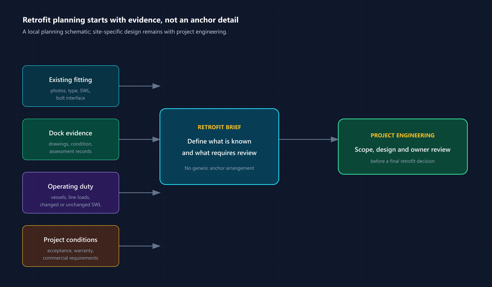
I recommend starting with the existing fitting because the replacement must suit what is already there. Collect its form, base-plate arrangement and marked SWL, together with available installation drawings, inspection findings and maintenance or damage records.
If no technical records exist, treat the structure as unknown until inspection or investigation verifies it. Both a pattern-matched bolt-hole replacement and a new anchorage solution remain candidate approaches, subject to the available evidence, project engineering and owner approval.
The pre-design evidence set should include bollard type and dimensions, the base-plate bolt-hole pattern and diameter, photographs of the bollard and surrounding concrete, the visible SWL marking, the intended SWL and berth-operating case, plus any available structural records. That allows a supplier to confirm whether a preliminary scope is possible or further evidence is needed.
For a budget enquiry, a smaller subset of inputs may be acceptable. Before technical or commercial evaluation, however, I would ask for the full package rather than assume an anchorage arrangement that might not satisfy the real project engineering review.
Which Mooring Loads and Operating Cases Must Be Defined?
A marked SWL on an existing bollard is not always a safe capacity for a changed berth or vessel duty. The intended load case must be defined before a retrofit is designed.
If the berth operating conditions remain unchanged and the intended SWL does not increase, the original bollard SWL may serve as a planning reference. If the berth will handle larger vessels, different mooring patterns or increased line loads, request the owner’s engineering company’s mooring analysis or provide vessel dimensions, berth exposure, fender reaction, line angle and environmental loading data so that a calculation can be prepared.
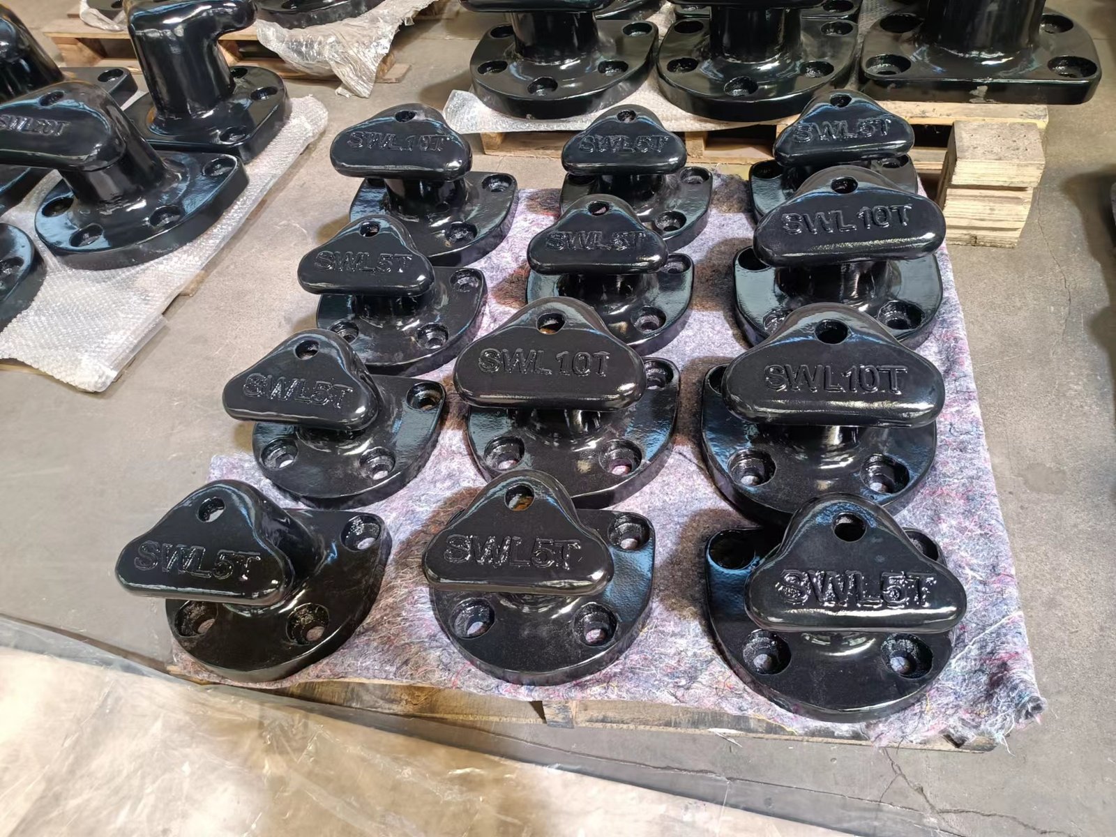
An SWL marking records the rating when the bollard was supplied. It does not verify the berth load, the foundation capacity or the capacity required for the retrofit. Larger vessels, changed mooring patterns or changed berth exposure can all alter the design case.
Where the operating conditions are genuinely unchanged and the intended bollard SWL matches the original rating, the original SWL can be retained as the design reference. That assumes the existing foundation was adequate and that no damage, degradation or unapproved load event has reduced the original capacity. If either assumption is uncertain, the project needs a condition review or a load verification step.
Where operating conditions have changed or the terminal requires a higher SWL, the owner’s engineering company should perform a mooring analysis using the actual vessel dimensions, berth geometry, fender reaction, line angle, wind and current loads, plus applicable project guidance. The resulting design loads become inputs for the bollard, base plate, anchors and supporting-concrete review.
I would not increase an SWL because an operator asks for it or a catalogue shows a higher nominal rating. It must be calculated and reviewed against the existing or proposed foundation; an assumed rating can be either wasteful or unsafe.
For broader quay-wall mooring-assessment context, PIANC lists Mooring of Large Ships at Quay Walls among its MarCom publications. It is further reading only, not a substitute for a project-specific mooring analysis or the owner’s engineering approval.
How Should the Existing Concrete and Reinforcement Be Investigated?
An anchorage transfers load into a concrete structure. The retrofit cannot be engineered unless the existing concrete and reinforcement are established.
Request the original dock drawings, concrete grade, cover depth and reinforcement layout if they exist. If records are missing, the owner’s appointed engineer must define the scope, methods and evidence appropriate to the actual structure before a design decision can be made. The investigation should establish the reinforcement position, concrete grade, cover depth, existing damage and any feature that could constrain the anchorage location or design.
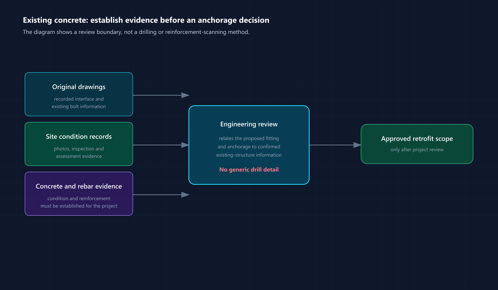
The existing concrete is usually unknown to the bollard supplier. The original dock may have been built decades ago, and the installation drawings may not exist. Even when drawings are available, they may not reflect what was actually constructed. The supplier needs the concrete grade, reinforcement type, bar size, spacing and cover depth to prepare an anchorage design or to verify that a pattern-matched bolt replacement may be acceptable.
If the project cannot supply that information, the dock owner or contractor must commission a site investigation. The owner’s appointed engineer must define the investigation scope, the extent of the survey zone around the bollard base, and the evidence required to support the retrofit design. The investigation output should include a reinforcement map, concrete test results, an assessment of the existing condition and a statement of any constraint such as a heavily reinforced zone, shallow cover or existing feature that could affect the retrofit design.
I recommend completing the investigation before the anchorage design is finalised. An anchorage solution can usually be adjusted to avoid clashing with existing reinforcement, but that adjustment depends on knowing where the reinforcement is. A pattern-matched replacement depends on confirming that the existing holes are free of obstruction and that the surrounding concrete can support the design load.
How Is the Bollard-to-Structure Load Path Established?
A bollard does not resist mooring loads alone. The load path runs from the vessel line through the bollard, base plate, anchor rods and into the supporting concrete.
Review the complete load path with the owner’s engineering company. The bollard design must be verified for the design load. The base-plate dimensions and thickness must resist the applied moment and bolt reaction. The anchor rods must transfer the tension and shear forces into the concrete. The concrete must support those forces without exceeding its capacity or failing around the anchor embedment zone.
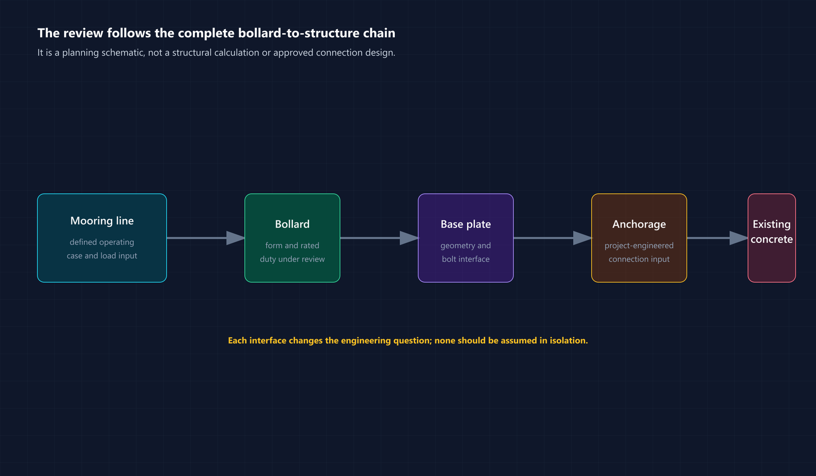
The bollard is only one part of the system. The base plate distributes the overturning moment to the anchor rods, which transfer load into the concrete and surrounding reinforcement. If any link is under-designed or under-verified, the system can fail before the bollard reaches its rated load.
JettyGuard can provide a strength-calculation report for its bollard design, for the owner’s engineering company to review. The project must allocate anchor-design responsibility and obtain the applicable engineering review.
The owner’s engineering company should verify that the existing or proposed foundation can support the anchor loads. The appropriate method depends on the retrofit complexity and available structure information; where required, the owner may separately scope combined FEA of the bollard, anchors and concrete.
I would not accept a bollard quotation that assumes the foundation is adequate. The complete load path must be reviewed before approval.
Which Anchor and Base-Plate Inputs Require Project Engineering?
A bollard base plate has bolt holes. The anchorage must align with those holes and transfer load into the concrete. The design of that interface depends on whether the retrofit reproduces the existing pattern or introduces a new anchorage.
For a pattern-matched replacement, verify that the new bollard base-plate bolt pattern matches the existing holes in position and diameter, that the existing anchorage or sleeves are sound, and that the design load does not exceed the original capacity. For a new anchorage retrofit, the responsible design party must confirm the design loads, base-plate dimensions, bolt-hole pattern, concrete grade, reinforcement position and any design constraints as engineering inputs.
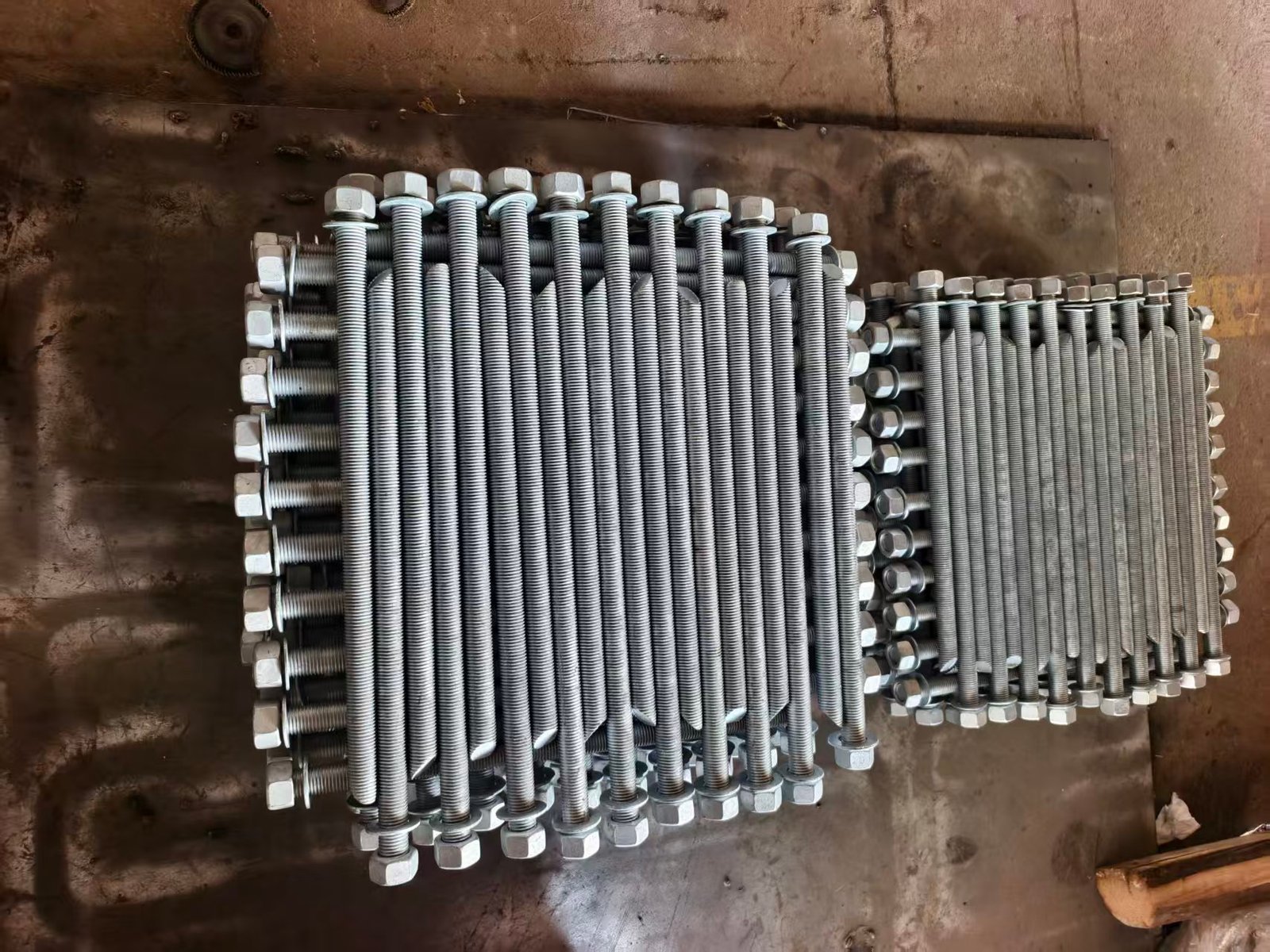
Both a pattern-matched replacement and a new anchorage retrofit are candidate approaches subject to the available evidence, project engineering and owner approval. The pattern-matched approach may be considered when the existing bolt-hole positions are known, the replacement bollard can be manufactured with a matching base-plate pattern and the retrofit does not increase the required SWL. That approach avoids new penetrations in the concrete and may allow the replacement to use the existing anchorage studs or sleeves. The supplier must confirm that the new bollard base-plate thickness, hole diameter and overall dimensions match the original interface before proceeding.
A new anchorage retrofit may be considered when the existing bolt pattern is not known, when the new bollard has a different interface, or when the required SWL increases. The anchorage design must then account for the concrete grade, reinforcement position and the applied tension, shear and moment loads. The solution selection and all concrete requirements are subject to evidence, allocated project design responsibility and owner engineering review and approval.
The engineering inputs include the bollard base-plate dimensions and bolt-hole layout, the design tension and shear load per bolt, the concrete grade and thickness, the reinforcement position and any constraint. The output should include the anchorage specification and a design check against the relevant code.
I would not propose a specific anchorage configuration in this article because those values depend on the project-specific loads, concrete condition and engineering review. The anchorage is not a catalogue selection. It is a structural interface that must be engineered for the real project condition.
How Should Installation Be Sequenced Around an Operating Dock?
A retrofit on an operating dock must be planned so that the work does not prevent berthing, create a safety hazard or damage the existing structure.
Before scheduling installation, obtain the owner’s written approval for the retrofit design, confirm the berth shutdown or access window, and agree the method statement, outage or access plan, and project acceptance criteria. The contractor must use an owner-approved method statement, permits and operational controls. The owner or operator determines outage, access and acceptance conditions.
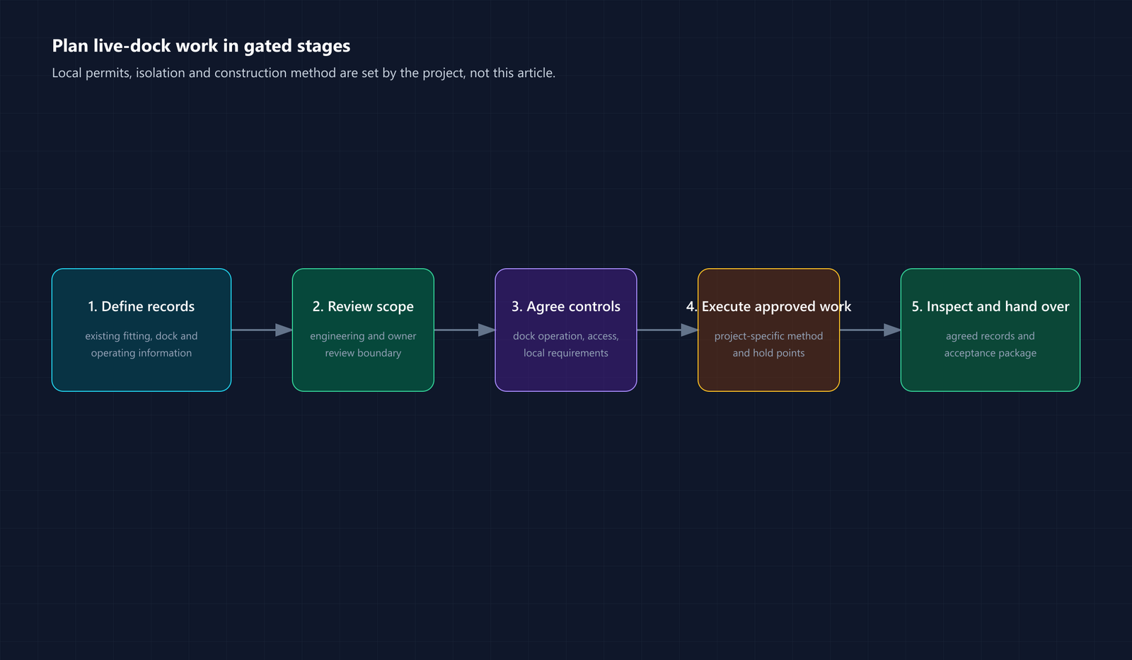
The dock may be in continuous use. The terminal may have strict safety and environmental controls. The berth may have limited access or constrained crane availability. The project must define how the work will be sequenced so that it fits within those constraints without forcing an unplanned shutdown or creating a risk.
The planning sequence starts with the owner’s approval of the retrofit design and supporting calculations. That approval confirms that the bollard, anchorage and foundation design have been reviewed and accepted by the owner’s engineering company. After approval, the contractor prepares a method statement and work plan that the terminal operator must review and approve.
For an operating dock, the work may need to be scheduled during a berth closure window or performed in stages so that adjacent berths remain available. The contractor must coordinate with the terminal operator to confirm access, crane availability, power supply and any permit requirement. The work zone should be isolated with barriers, and the active berth should not be used until the new bollard is installed and accepted.
I would not prescribe a construction sequence or permit process because those depend on local regulations, the terminal’s safety management system, the specific dock layout and the approved method statement. The responsibility for safe installation lies with the contractor and the terminal operator.
What Inspection, Testing and Handover Evidence Should Be Required?
A bollard retrofit should include agreed documentation that demonstrates the product conforms to the design and that the installation satisfies the acceptance criteria.
Agree the required documentation before the contract is placed. Product records may include material test certificates, non-destructive testing reports, dimensional inspection records, hot-dip galvanizing certificates and coating thickness reports depending on the project specification. Load testing and third-party inspection may be separately scoped if the project requires them. Installation records must be defined by the project specification and approved method statement. The handover package should be defined in the RFQ and confirmed in the purchase order.
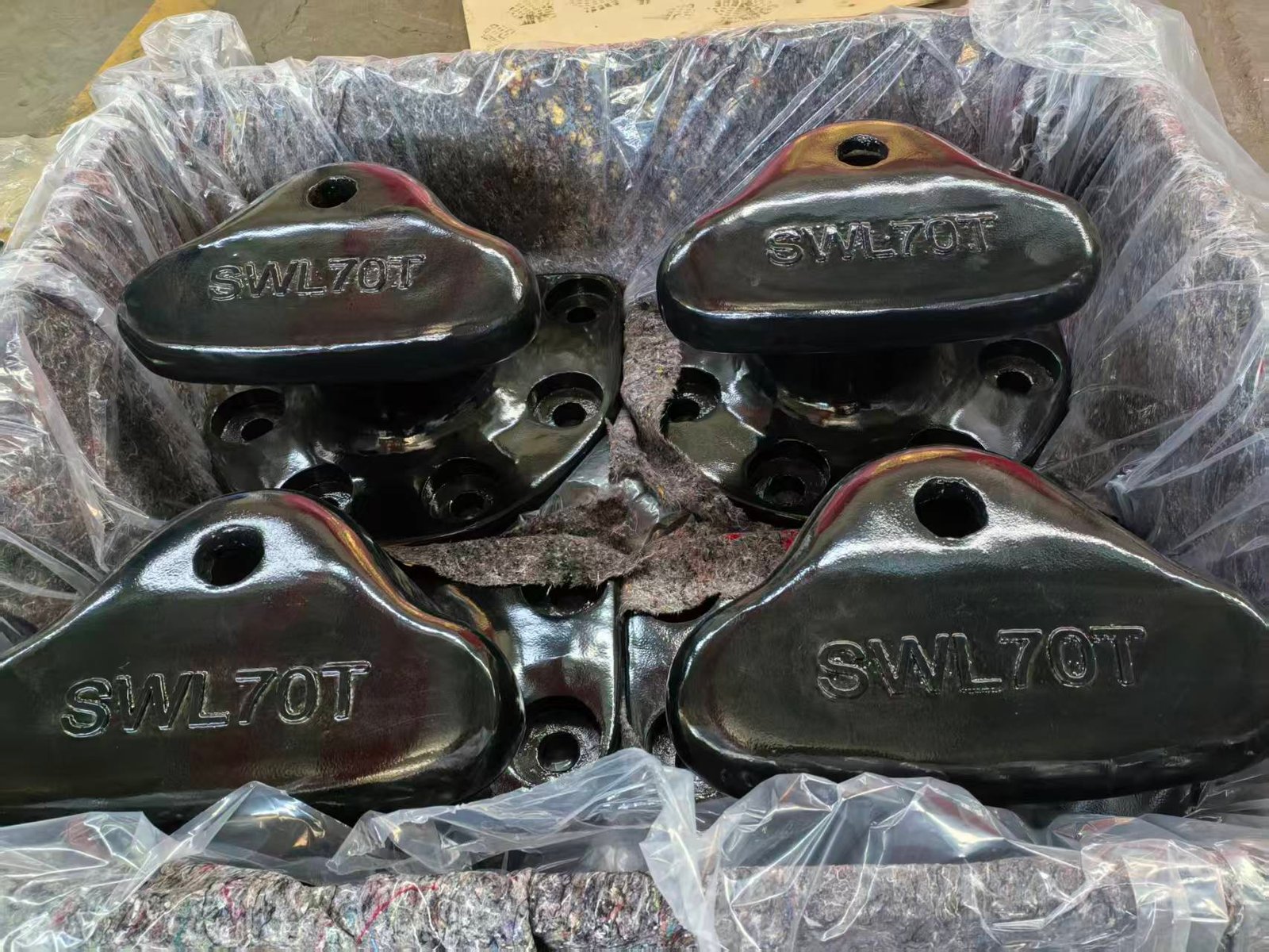
The type and quantity of inspection evidence depend on the project’s technical requirements and acceptance process. JettyGuard can provide a strength-calculation report for its bollard design. Product documentation that may be available includes non-destructive testing records, hot-dip galvanizing certificates, dimensional inspection results, material test certificates and coating thickness reports, subject to project scope. A paid load test and third-party inspection can be separately scoped if the project requires them.
The bollard design is reviewed by the owner’s engineering company. The foundation design may be verified by the owner’s structural engineer or by a separately contracted analysis. Installation records should confirm that the retrofit was completed to the approved method statement and that the bollard was positioned within tolerance.
I recommend defining the full document package in the RFQ and purchase order, not adding reports after manufacture or installation. Material certificates, paid load testing and third-party inspection each affect cost and lead time, so they must be planned within the project scope.
The handover package should include all agreed product records, the bollard strength-calculation report, installation records and any load-test or inspection certificate that was contracted. The terminal operator or owner’s representative should inspect the installed bollard and confirm that it is positioned correctly and that the bollard marking matches the agreed SWL.
What Should Be Included in a Bollard Retrofit RFQ?
A complete RFQ allows the supplier to prepare a responsible technical and commercial response. An incomplete RFQ risks receiving offers that are not comparable or that omit essential inputs.
For a budget enquiry, provide the bollard type and nominal SWL, the approximate base-plate or anchorage interface, the delivery location and the expected quantity. For a technical or commercial evaluation, add the existing bollard photographs and drawings, the original bolt pattern or proposed anchorage arrangement, the design load case or mooring analysis result, the concrete grade and reinforcement evidence, the required product documentation and acceptance criteria, the payment terms and the warranty requirement.
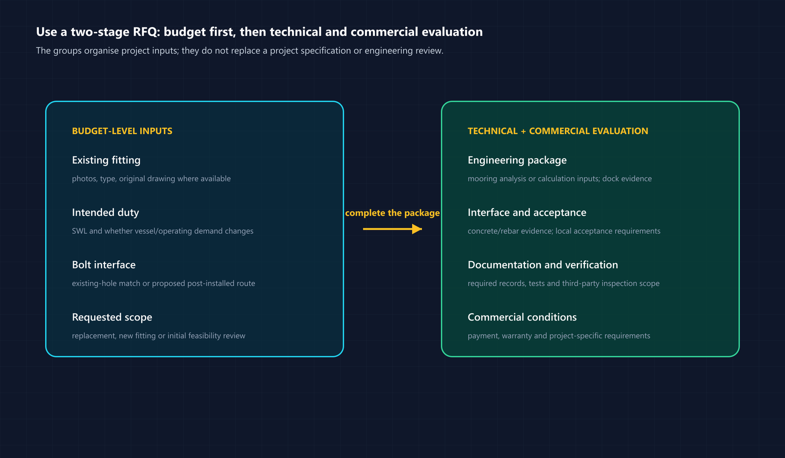
A basic RFQ that asks only for a bollard type and SWL can produce a budget price. That price may allow the terminal to compare suppliers or to confirm that the retrofit is financially feasible. It does not allow the supplier to verify that the bollard will fit the existing interface, that the foundation can support the load or that the project has satisfied the engineering boundary.
Before technical or commercial evaluation, the RFQ should include enough information for the supplier to assess whether the retrofit is feasible. That information includes the existing bollard photographs, original installation drawings if available, the bolt-hole pattern or the proposed anchorage approach, the design load case or mooring analysis summary, the concrete grade and reinforcement position, any constraint and the required product documentation such as material certificates, NDT reports or load testing.
The RFQ should also define the commercial boundary. That includes the delivery terms, the payment structure, the warranty duration and scope, the inspection or testing requirement, the installation responsibility and the handover acceptance criteria. Without those terms, the supplier may quote one scope while the buyer expects another, and the difference will surface only when the purchase order is negotiated.
I would pause before issuing a technical RFQ if the existing structure has not been investigated or if the design loads have not been defined. A supplier may respond with an assumed solution, but that assumption cannot be relied upon for project approval. The project should collect the evidence first, then request a responsible offer based on that evidence.
Conclusion
A mooring bollard retrofit on an existing concrete dock begins with evidence, not a product selection. Define the existing fitting, the intended SWL and operating case, the concrete and reinforcement condition and the engineering boundary before requesting a design or price. JettyGuard provides mooring bollards with strength-calculation reports for owner engineering review. Where required, paid FEA and project documentation packages can be separately scoped.