
Pneumatic Fenders · ISO 17357-1:2014
Pneumatic Fenders for LNG Terminals, FSRU Mooring, and Offshore Berthing
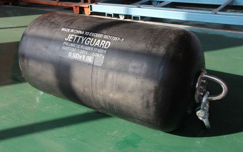
Every LNG and FSRU project carries a documentation requirement that most suppliers can't meet. JettyGuard supplies ISO 17357-1:2014 certified pneumatic fenders — 500×1000 mm to 4500×9000 mm — with prototype testing per Clause 8, BV/DNV/ABS third-party inspection per Clause 12, and complete FAT documentation packages.
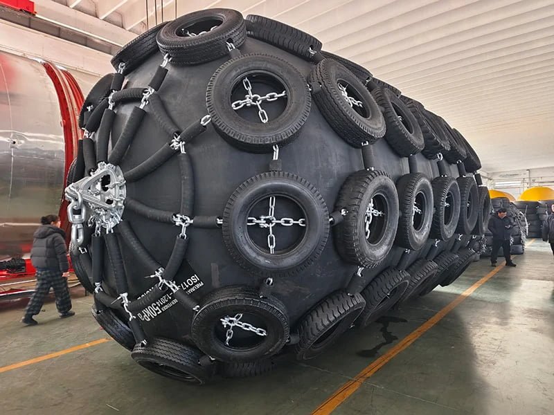
Pneumatic fenders — also called Yokohama-type fenders — are self-floating, rubber-and-compressed-air fenders used for LNG carrier berthing, FSRU mooring, and ship-to-ship (STS) transfer operations. Standard sizes range from 500×1000 mm to 4500×9000 mm, with energy absorption from 9 kJ to over 9,350 kJ at 50 kPa initial inflation pressure, conforming to ISO 17357-1:2014.
Definition
What Is a Pneumatic Fender?
A pneumatic fender is a floating fender element consisting of a reinforced rubber body inflated to a specified initial internal pressure — typically 50 kPa or 80 kPa — which absorbs berthing energy through controlled compression of the air charge inside the fender body. As the vessel applies load, the fender deflects and the internal pressure rises, generating a controlled reaction force against the hull while dissipating kinetic energy.
The term “Yokohama-type fender” derives from the fender’s origin as a large pneumatic rubber buoy developed in Japan in the 1950s and now manufactured globally to a standardized format. In current engineering practice, “Yokohama fender” and “pneumatic fender” are used interchangeably, with ISO 17357-1:2014 serving as the governing international standard for product classification, performance testing, and dimensional tolerances.
Pneumatic fenders are the standard selection for applications where hull pressure limits are critical, where the fender must operate in a floating, unsupported mode — such as ship-to-ship (STS) transfer — or where the interface involves two floating vessels rather than a vessel approaching a fixed quay. They are widely specified at LNG import and export terminals, FSRU berths, offshore oil STS operations, and shipyard mooring locations per PIANC, OCIMF, and SIGTTO guidance.
Applications
Where Pneumatic Fenders Are Specified — and What Drives the Sizing Decision
The application drives the fender size, IIP, net type, and certification class. The four contexts below cover the scenarios in which ISO 17357 pneumatic fenders are the primary specification — with typical size ranges and key selection factors for each.
LNG Terminal
LNG Terminal Berthing — High Energy, Low Hull Pressure
Fixed LNG import and export terminals require fenders capable of absorbing high berthing energy from large LNG carriers — vessels ranging from 75,000 m³ to 270,000 m³ displacement — while maintaining hull pressure within limits acceptable for both the carrier hull plating and the jetty structure. Pneumatic fenders are widely preferred here because their energy-absorption-to-reaction-force ratio allows high energy uptake without generating excessive contact pressure on sensitive hull sections.
For standard LNG terminals receiving carriers in the 125,000–175,000 m³ range, 3300×6500 mm and 4000×8000 mm are the most common specification points. Selection must be confirmed against approach velocity, effective berthing energy, hull pressure limits, and berth geometry per PIANC MarCom Report No. 211 (2024).
Standard references: PIANC MarCom Report No. 211 (2024), ISO 17357-1:2014, PIANC 2002
Submit Your LNG Terminal Specification →FSRU / FSU
FSRU Side-by-Side Mooring — Relative Motion, Extended Contact, Highest Load Case
Floating Storage and Regasification Units (FSRUs) present a more demanding fender selection case than fixed terminal berthing. When an LNG carrier moors alongside an FSRU for gas transfer, both hulls are in motion — responding independently to wind, wave, and current. The effective berthing energy must account for relative motion between the two floating bodies, not simply the approach velocity of the arriving vessel.
In FSRU side-by-side configurations, pneumatic fenders are suspended from the FSRU hull using chain-tire net rigging, with sling arrangements configured to match vessel freeboard and operating geometry. Fender size, quantity, and layout are governed by SIGTTO FSRU Mooring and Fender Guidelines and OCIMF Mooring Equipment Guidelines (4th edition). In our experience supplying FSRU operators, 4000×8000 mm and 4500×9000 mm are the most common sizes for LNG carrier interfaces, though final selection depends on the specific vessel pair and operating environment.
Standard references: SIGTTO FSRU Mooring and Fender Guidelines, OCIMF Ship-to-Ship Transfer Guide, ISO 17357-1:2014
See dedicated guidance on pneumatic fenders for FSRU and LNG terminal applications.
Request an FSRU Fender Sizing Review →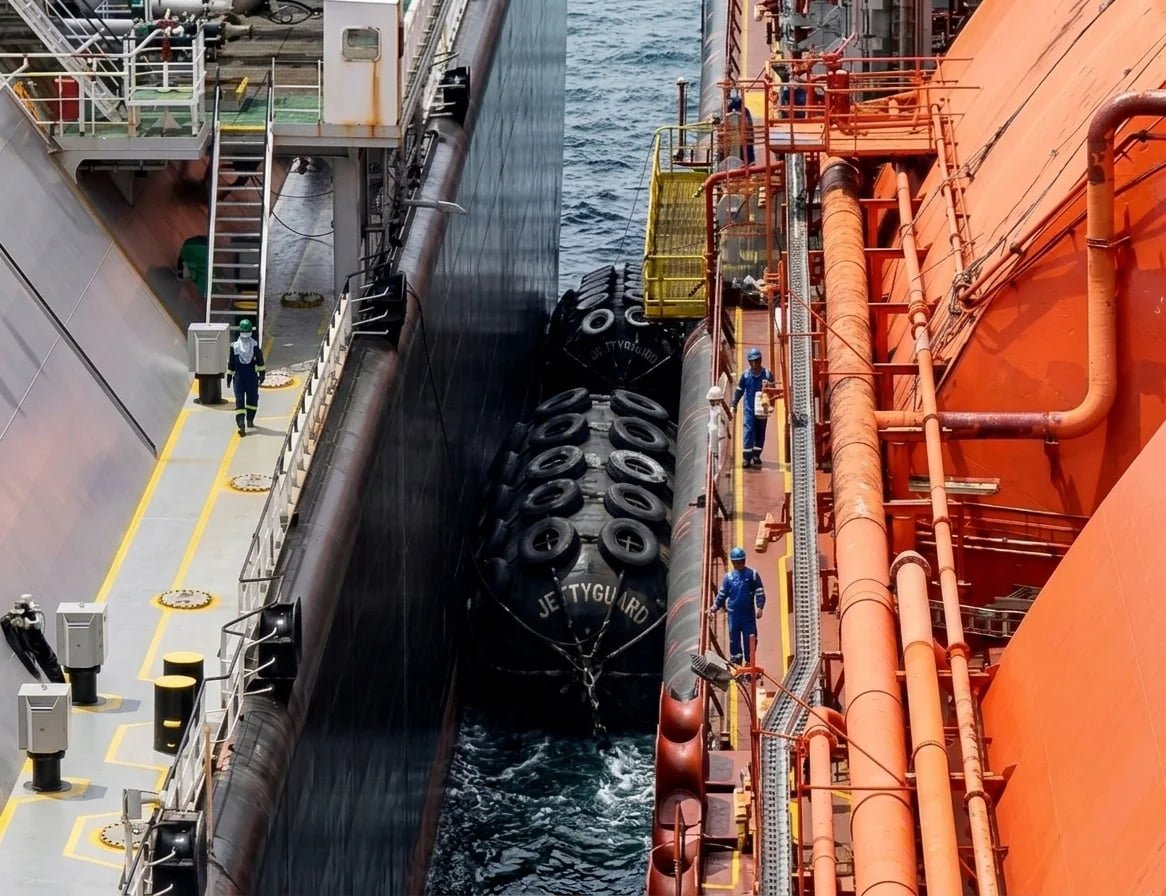
STS / Marine Transfer
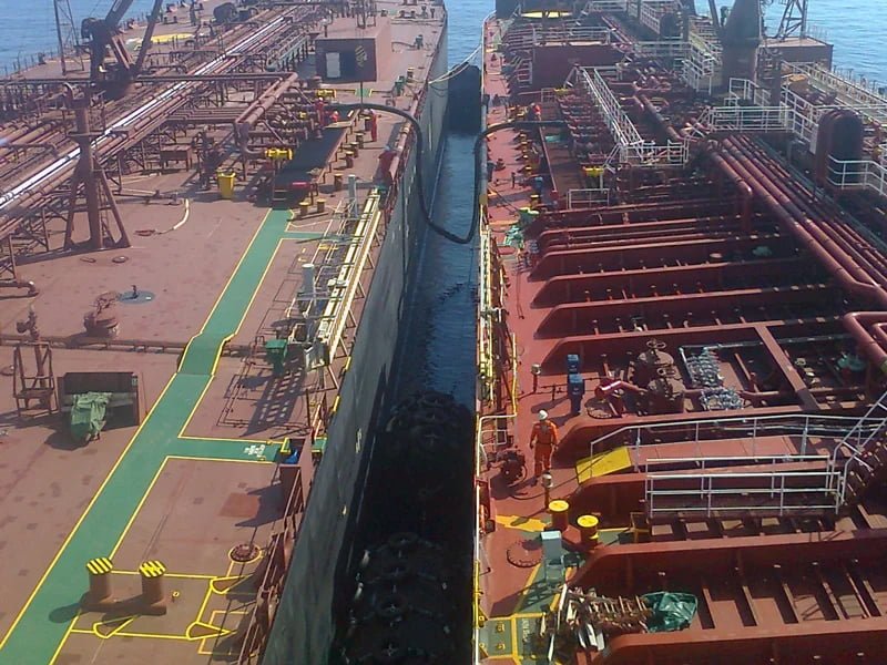
Ship-to-Ship (STS) Transfer — Fender Must Float Free, Deploy and Recover Between Operations
Ship-to-ship transfer operations — whether LNG, crude oil, or refined product — require fenders that operate without any support from a fixed structure. The fender must maintain separation between two vessels in open water or alongside an offshore facility while the cargo transfer takes place, which can last many hours.
Pneumatic fenders are the standard choice for STS operations because they are self-floating, deploy without fixed mounting infrastructure, and can be retrieved and repositioned between operations. OCIMF STS Transfer Guidelines define minimum fender performance requirements for STS operations involving tankers, with pneumatic fenders conforming to ISO 17357-1:2014 meeting the standard specification basis for most commercial operators.
Standard references: OCIMF STS Transfer Guidelines, ISO 17357-1:2014
See dedicated guidance on ship-to-ship transfer fenders and STS operations.
Get STS Fender Specifications →Port & Offshore
General Port and Offshore Berthing — From 500×1000 mm Workboat Fenders to 2000×3500 mm Commercial Berths
Beyond LNG and STS applications, pneumatic fenders serve a wide range of port and offshore berthing scenarios: shipyard mooring fender systems, offshore platform supply vessel interfaces, floating dock separators, and general cargo terminal fender systems where a self-floating, low-maintenance fender element is preferred.
Smaller sizes — from 500×1000 mm to 1500×3000 mm — are commonly used for workboat and small vessel berths, navy vessel mooring, and intermediate dock applications. Larger sizes from 2000×3500 mm upward are appropriate for bulk carrier, tanker, and general cargo vessel interfaces at commercial port facilities.
Standard references: PIANC 2002, ISO 17357-1:2014
Request a Size and Specification Quote →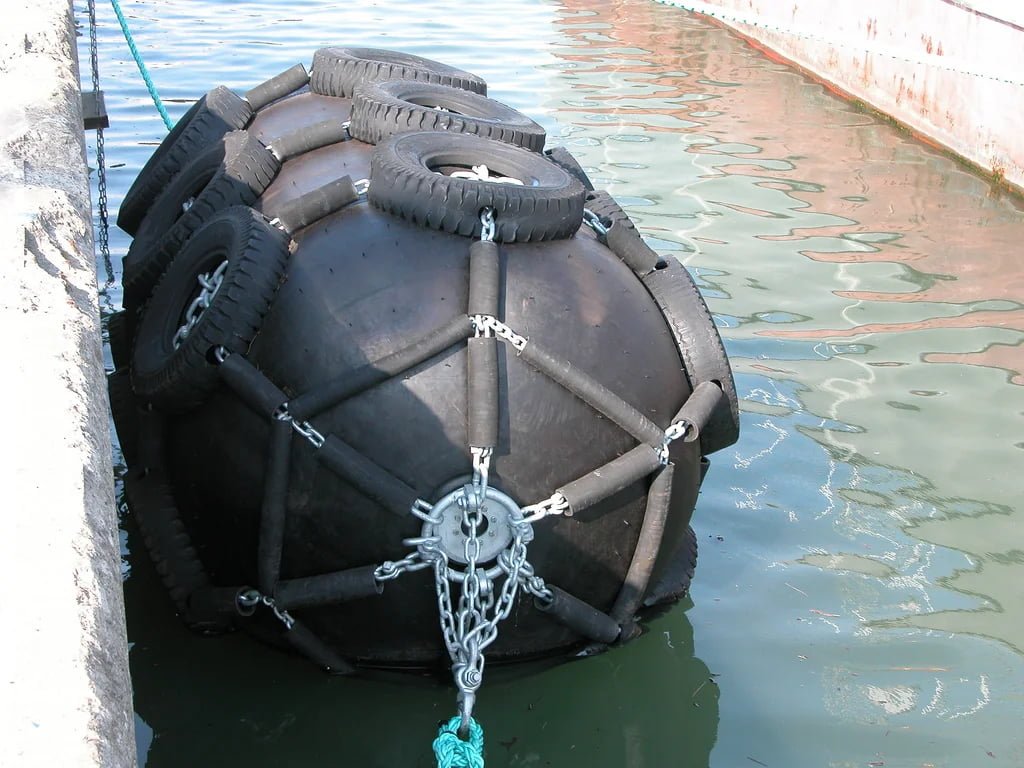
Specification Range
Pneumatic Fender Size Chart — ISO 17357 Standard Sizes
The table below covers JettyGuard’s standard pneumatic fender sizes from 500×1000 mm to 4500×9000 mm. Reaction force and energy absorption values are given at both 50 kPa and 80 kPa initial inflation pressure (IIP), at 60% rated deflection. Performance tolerance is ±10%.
| Fender Size (D×L mm) | RF at 50 kPa (kN) | EA at 50 kPa (kJ) | RF at 80 kPa (kN) | EA at 80 kPa (kJ) | Typical Application |
|---|---|---|---|---|---|
| 500 × 1000 | 64 | 6 | 80 | 8 | Small craft / workboat berth |
| 600 × 1200 | 86 | 10 | 108 | 13 | Small craft / workboat berth |
| 700 × 1500 | 137 | 17 | 171 | 21 | Small vessel / navy tender |
| 1000 × 1500 | 181 | 32 | 266 | 40 | Workboat / tug / small ferry |
| 1350 × 2500 | 426 | 100 | 533 | 125 | General cargo / coastal vessel |
| 1500 × 3000 | 579 | 153 | 724 | 191 | General cargo / small tanker |
| 1700 × 3000 | 637 | 190 | 796 | 238 | General cargo / small bulk carrier |
| 2000 × 3500 | 875 | 308 | 1,094 | 385 | Bulk carrier / medium tanker |
| 2500 × 4000 | 1,380 | 663 | 1,725 | 829 | Medium tanker / product carrier |
| 2500 × 5500 | 2,010 | 932 | 2,513 | 1,658 | LNG carrier < 75,000 m³ / large tanker |
| 3000 × 5000 | 2,030 | 1,050 | 2,538 | 1,313 | LNG carrier < 100,000 m³ / VLCC approach |
| 3300 × 6500 | 3,015 | 1,814 | 3,961 | 2,534 | LNG carrier 100,000–150,000 m³ / FSRU mooring |
| 3500 × 6000 | 3,286 | 2,018 | 4,018 | 2,523 | LNG carrier / VLCC STS |
| 4500 × 9000 | 5,747 | 4,752 | 7,551 | 6,633 | FSRU mooring / Q-Flex / VLCC / largest LNG carriers |
All values at 60% deflection of nominal diameter. Performance tolerance is ±10%.
IIP = Initial Inflation Pressure. Standard is 50 kPa (0.05 MPa). The 80 kPa option gives higher energy absorption and reaction force from the same body size — used where installation space is limited but energy requirement is high.
Final values for a specific project must be taken from manufacturer test certificates, not catalog tables.
Custom sizes outside the standard range are available on request. Diameter-to-length ratios other than the standard format can be produced for specific project geometries.
This table is intended for preliminary selection only. Final specification requires a project-specific berthing energy calculation per PIANC MarCom Report No. 211 (2024).
RFQ Support
Need Help Matching Fender Size to Your Project Energy Calculation?
Share your vessel class, berthing energy requirement, or hull pressure limit. JettyGuard can review the application and recommend a starting size for your specification.
Net Type Comparison
Chain-Tire Net (CTN) vs Sling Net: Which Rigging System Your Application Requires
Net-type pneumatic fenders (ISO 17357-1:2014 Type I) can be rigged with two kinds of protective cover fitted over the rubber body — a rope/nylon sling net or a chain-tire net. The choice depends on abrasion exposure, contact duration, and handling weight. (The alternative construction, ISO Type II sling-type, carries no protection net and is used in lighter-duty arrangements.)
Sling Net (Rope/Sling System)
This option uses a woven rope or nylon sling network fitted over the rubber body. The sling net distributes contact loads across the fender surface, protects the rubber from abrasion and impact, and provides the suspension attachment points for hanging arrangements. Sling-type fenders are lighter, easier to deploy and recover, and lower in cost than chain-tire net versions. They are preferred for applications where weight handling is a constraint, fender retrieval is frequent, or the operating environment is less severe.
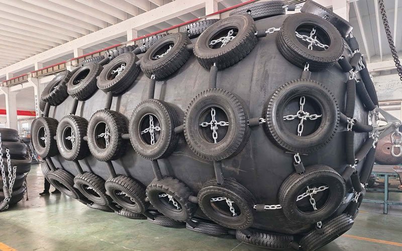
Chain-Tire Net (CTN)
This option uses a chain net system interwoven with rubber tire sections fitted over the sling base layer. The chain-tire net provides a higher level of mechanical protection against hull abrasion, vessel impact at low tide or extreme freeboard conditions, and chain wear during extended operational periods. CTN fenders are heavier but significantly more durable, making them the standard choice for FSRU mooring, LNG terminal fixed berths, and any application involving extended contact duration or higher frequency of use.
| Attribute | Rope / Sling Net | Chain-Tire Net (CTN) |
|---|---|---|
| Protective cover | Rope/nylon sling network | Chain net + rubber tire sections |
| Weight | Lighter | Heavier |
| Abrasion protection | Moderate | High |
| Durability in continuous use | Acceptable for infrequent deployment | Required for continuous terminal duty |
| Deployment and recovery ease | Easier | More complex due to weight |
| Typical application | STS operations, workboat berths, temporary fendering | LNG terminal fixed berths, FSRU hull-mounted primary fenders |
| Relative cost | Lower | Higher |
| Recommended for LNG/FSRU | Secondary or temporary use | Primary specification |
Recommendation: For FSRU mooring and fixed LNG terminal applications, the chain-tire net (CTN) is the standard specification. For STS operations where the fender must be deployed and recovered between transfers, lighter rope/sling-net fenders are often used in combination with a CTN primary fender.
Manufacturing Method
Mold-Process vs Wrapped-Process: Why Manufacturing Method Affects Your Project Certification
Pneumatic fenders are manufactured using one of two production methods. The method determines rubber wall consistency, fatigue life, dimensional accuracy, and suitability for high-frequency or critical applications.
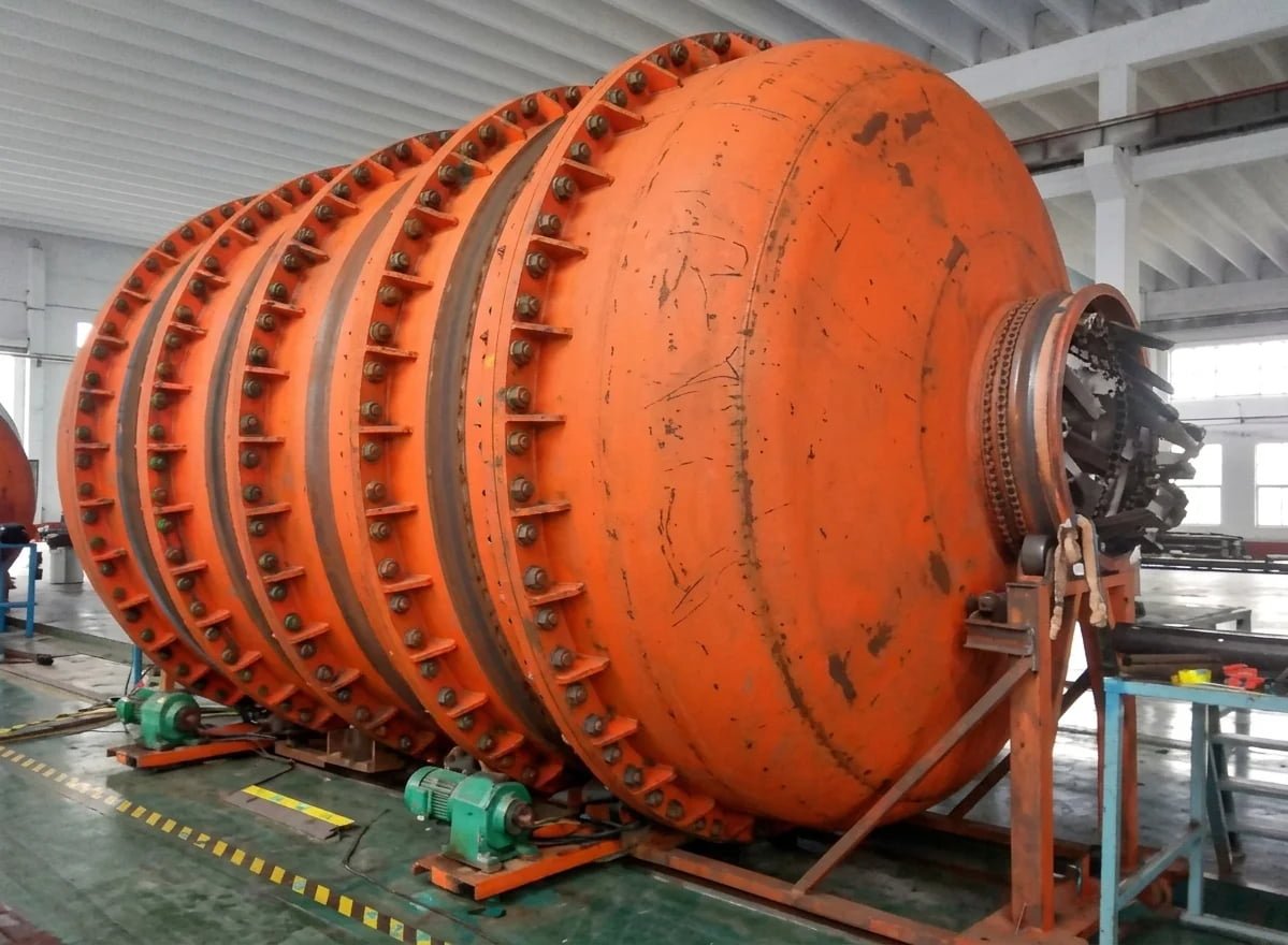
Mold-Process Manufacturing
In mold-process (also called press-mold or vulcanization-mold) production, the rubber body is formed inside a precision steel mold under controlled heat and pressure. The mold maintains consistent wall thickness throughout the fender body during vulcanization. The result is a fender with uniform rubber density, predictable performance characteristics, and consistent dimensional accuracy across production batches.
Mold-process fenders are the correct choice for LNG terminal and FSRU applications where performance certification, high cycle frequency, and extended service life are required.
Wrapped-Process Manufacturing
In wrapped-process (also called hand-built or calendar-wrapped) production, the rubber body is built up by wrapping successive layers of uncured rubber sheet and reinforcing fabric around a mandrel, then vulcanizing the assembly in an autoclave. This method accommodates larger diameter bodies and non-standard sizes but results in less uniform wall thickness compared to mold-process production.
Wrapped-process fenders are suitable for cost-sensitive applications at standard commercial ports, where certification requirements are less stringent and fender replacement cycles are longer.
| Attribute | Mold-Process | Wrapped-Process |
|---|---|---|
| Wall thickness consistency | High — mold-controlled | Moderate — manual process |
| Dimensional accuracy | High | Moderate |
| Fatigue life | Longer | Shorter |
| Performance test repeatability | High | Moderate |
| Suitability for ISO 17357-1:2014 Clause 8 prototype testing | Well-suited — repeatable test results | Acceptable for Clause 9 commercial fender testing; prototype test results may show higher variance |
| Suitable for FSRU / LNG terminal | Recommended | Not recommended for critical use |
| Suitable for standard port | Appropriate | Appropriate |
| Custom sizes outside ISO range | Limited by mold size | More flexible |
JettyGuard Recommendation: For FSRU mooring, LNG terminal berthing, and any project requiring third-party inspection (BV, DNV, ABS), we recommend mold-process fenders — and supply them as our standard for all critical applications. Wrapped-process fenders are appropriate for cost-controlled procurement at standard port facilities where Clause 9 commercial fender testing is sufficient.
Product Comparison
Pneumatic Fender vs Foam-Filled Fender: Which Is Correct for LNG, FSRU, and STS Applications?
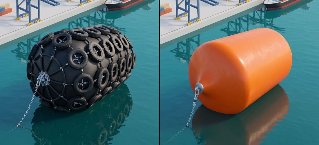
Both pneumatic and foam-filled fenders are self-floating fender types used in offshore and marine berthing applications. The selection between them is determined by application requirements, hull pressure sensitivity, standards compliance, and maintenance context.
| Attribute | Pneumatic Fender | Foam-Filled Fender |
|---|---|---|
| Energy absorption mechanism | Compressed air — pressure rises as fender deflects | Foam core compression — constant resistance characteristic |
| Buoyancy | Self-floating via air charge | Self-floating via closed-cell foam core |
| Hull pressure at rated deflection | Lower — typically within LNG carrier hull pressure limits | Higher — often exceeds LNG carrier hull pressure limits |
| LNG carrier suitability | Preferred — low hull pressure profile | Limited — hull pressure typically exceeds limits |
| FSRU berthing suitability | Standard specification | Not commonly used for FSRU primary fender |
| STS transfer suitability | Standard choice — self-floating, deployable | Used in some STS contexts, but pneumatic is more common |
| Governing standard | ISO 17357-1:2014 — required by OCIMF and SIGTTO | No equivalent ISO product standard |
| OCIMF / SIGTTO compliance | Compliant — referenced in OCIMF STS guidance | Not specifically referenced |
| Maintenance requirement | Periodic pressure monitoring; valve and plug inspection | Lower routine maintenance — no pressure management |
| Consequence of damage | Performance degrades if punctured (air loss) | Foam core retains buoyancy even if outer skin is damaged |
| Service life | 10–20 years with correct IIP management | 10–15 years, dependent on foam quality and UV exposure |
Conclusion: For LNG carrier berthing, FSRU mooring, and STS transfer operations where SIGTTO, OCIMF, or PIANC compliance governs the specification, pneumatic fenders are the primary selection. Foam-filled fenders have a role in applications where maintenance simplicity and penetration resistance outweigh the hull pressure advantages of the pneumatic type. For a detailed side-by-side technical comparison, see our dedicated pneumatic fender vs foam-filled fender comparison page.
Specification Review
Not Sure Whether Pneumatic or Foam Is Right for Your Project?
Send your application details and we'll advise on the correct fender type, size, and certification scope for your project.
Standards & Certifications
Standards, Certifications, and What They Mean for Your Project Documentation
ISO 17357-1:2014 — Floating Pneumatic Rubber Fenders
ISO 17357-1:2014 is the primary international standard governing pneumatic fender design, materials, dimensional tolerances, performance testing, and product classification. It defines a three-tier quality framework: Clause 8 (prototype performance testing, valid 10 years), Clause 9 (commercial batch testing for every production order), and Clause 12 (optional third-party independent inspection by BV, DNV, ABS, or Lloyd's Register). For LNG, FSRU, and STS applications, buyers should specify Clause 12 third-party inspection in the procurement specification.
PIANC MarCom Report No. 211 (2024)
PIANC MarCom Report No. 211 (2024) is the current technical reference for fender selection, energy calculation, and layout design for LNG import and export terminals, FSRUs, and related floating facilities. It supersedes the general fender design guidance in PIANC 2002 for LNG-specific applications and provides updated methodology for berthing energy calculation, hull pressure analysis, and fender arrangement.
OCIMF Ship-to-Ship Transfer Guide
The OCIMF Ship-to-Ship Transfer Guide is the governing reference for STS fender selection and berthing energy — its Appendix H sets out the fender selection calculation and size/energy tables for STS operations involving oil tankers and LNG carriers. It defines the energy envelope and hull-pressure verification the fender arrangement must satisfy. (The separate OCIMF Mooring Equipment Guidelines, MEG4, cover mooring equipment such as lines and winches.)
SIGTTO FSRU Mooring and Fender Guidelines
SIGTTO publishes specific guidance for FSRU mooring systems, including fender configuration, minimum number of fenders per side, sling angle requirements, and operational inspection criteria. For any project involving an FSRU as the receiving or transfer terminal, SIGTTO guidelines should be consulted alongside PIANC 211 for fender layout and sizing.
PIANC 2002 — Guidelines for the Design of Fender Systems
PIANC 2002 remains the foundational reference document for berthing energy calculation methodology and is still widely cited in engineering specifications and legacy project documentation. It defines the effective berthing energy formula, the abnormal berthing factor, and acceptable hull pressure limits for vessel types.
Third-Party Inspection: BV, DNV GL, ABS, Lloyd’s Register
JettyGuard coordinates third-party inspection directly with Bureau Veritas (BV), DNV GL, ABS, and Lloyd’s Register — we manage the inspection scheduling so it is incorporated into the production and delivery plan, not bolted on afterward. Certification scope can cover factory inspection, dimensional verification, pressure testing, performance testing at rated IIP, and full documentation packages.

Supply Scope
Supply Scope and Lead Times — What to Expect from a JettyGuard Order
Full ISO 17357 Size Range — 500×1000 mm to 4500×9000 mm
JettyGuard supplies pneumatic fenders across the full ISO 17357 standard size range, from 500×1000 mm to 4500×9000 mm. Project-specific sizes outside the standard range — including non-standard diameter-to-length ratios — can be reviewed on request.
50 kPa or 80 kPa Initial Inflation Pressure
Standard initial inflation pressure is 50 kPa (0.05 MPa). 80 kPa (0.08 MPa) fenders are available for applications requiring higher energy absorption from the same body size. IIP selection should be confirmed against the project energy calculation and hull pressure limits before ordering.
Rigging and Accessories
Pneumatic fenders can be supplied complete with chain-tire net or rope/sling-net rigging systems, shackles, swivels, and suspension hardware. For FSRU and LNG terminal projects, we supply complete rigging packages designed for the specific fender size and vessel interface geometry. See our marine rigging gear and fender accessories page for full accessory scope.
Full Documentation Package — MTC, Dimensional Reports, Performance Certificates, FAT Records
Available documentation includes material test records, dimensional inspection reports, inflation pressure test records, and performance test certificates. Third-party inspection can be coordinated with BV, DNV GL, ABS, or Lloyd’s Register per project quality plan requirements.
Lead Times: 4–8 Weeks Standard, 8–14 Weeks for ISO 17357-1:2014 with Clause 12 Third-Party Inspection
Standard commercial-grade sizes (non-certified) can typically be supplied within 4–8 weeks from order. ISO 17357-1:2014 orders with Clause 12 third-party inspection require 8–14 weeks depending on inspection body availability and test schedule. Project lead time should be discussed at the inquiry stage.
Frequently Asked Questions
Common Specification Questions — Answered by JettyGuard’s Engineering Team
What is a pneumatic fender?
What size pneumatic fender do I need for an LNG carrier?
What testing and inspection levels does ISO 17357-1:2014 define?
Check your project’s inspection requirements — ask our team →
Pneumatic fender vs foam fender — which is better for STS?
Not sure which fender type fits your STS operation? Ask us →
How long do pneumatic fenders last?
What certifications does JettyGuard offer?
Can I get a custom size pneumatic fender?
Specification Review
Ready to Specify? Send Us Your Project Parameters.
Share your project parameters below — vessel class, terminal type, fender size or energy requirement, and certification scope if known. Our engineering team reviews every inquiry and responds with a fender recommendation and commercial offer within two business days.
Not sure what to include?
Don’t have full specifications yet? That’s normal. Share what you know — vessel type, application, rough fender size, or just the project stage. Our engineering team will identify the right questions and respond within two business days with a sizing recommendation.
Our engineering team responds within two business days with a fender size recommendation and commercial proposal.
Specification Review
Need a Pneumatic Fender Specification Review?
Send your LNG, FSRU or STS project parameters. We'll review and respond with a sizing recommendation and commercial offer.
Request a Specification Review