Engineers planning an LNG berth, an FSRU mooring layout, or a ship-to-ship transfer station usually arrive at the same fork in the road: pneumatic fender or cone fender. The two products are not interchangeable, and picking by feature spec alone is the wrong starting point. The right question is what kind of berth you are building.
Pneumatic fender vs cone fender comes down to berth type. Cone fenders are bolted to a fixed quay, dolphin or pile and handle ship-to-shore berthing on permanent terminals. Pneumatic fenders float between two hulls or between a hull and a fixed structure, and are the default choice for STS, FSRU mooring and retrofits where the fender system must be mobile.

What is a pneumatic fender?
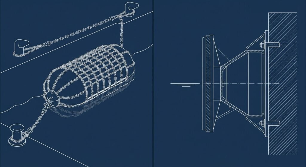
A pneumatic fender is a floating rubber fender filled with pressurized air. The reinforced rubber body deflects under impact and absorbs berthing energy through air compression, not rubber shear. Sizes follow the ISO 17357 standard size tables and pressure ratings (Pneumatic 50 / Pneumatic 80), so a buyer can specify a 2.5 m × 5.5 m Pneumatic 50 unit directly on the purchase order.
The fender is held in service by chains, tyre nets and shackles. It can be moved between berths, carried on a workboat, or repositioned between two vessels for ship-to-ship transfer. Our pneumatic fender product line and the Yokohama-type pneumatic fenders we supply both follow this ISO size scheme.
Because the unit floats and is not bolted to any structure, the same fender can serve a fixed berth, a barge, an FSRU, or a mother-vessel during STS. The trade-off is service life: a pneumatic fender is a wear item with a 10 to 15 year replacement window in heavy duty.

What is a cone fender?
A cone fender is a solid rubber fender shaped like a truncated cone, bolted to a fixed structure with a steel frontal panel facing the vessel. It absorbs berthing energy through rubber deformation. Performance is project-specific: berthing energy is calculated for the design vessel, then a cone size and rubber compound are selected.
Cone fenders are not interchangeable units. The cone diameter, height, rubber grade, panel size, and anchor pattern are all designed against a specific berth load case. Replacement is a civil works job, not a marine works job, because the anchor bolts sit in the concrete or the steel pile.
A common point of confusion: cone fender, cell fender, and super-cone are related but different geometries. This article uses cone fender in the common B2B sense covering modern compression-type rubber fenders with a frontal panel.

Pneumatic fender vs cone fender: side-by-side comparison
The table below compares the two families across the axes that actually drive procurement and design decisions. Most fender selection arguments collapse into one of these rows.

| Axis | Pneumatic fender | Cone fender |
|---|---|---|
| Installation | Floating, chain-moored | Bolted to fixed structure |
| Berth structure | Quay, dolphin, hull, FSRU side, barge | Concrete quay, steel pile, dolphin |
| Energy absorption profile | Softer curve, energy stored as compressed air | Steeper curve, energy stored as rubber strain |
| Reaction force on hull | Lower at high deflection | Higher at full deflection |
| Hull pressure distribution | Spread over a wider footprint | Concentrated under the frontal panel |
| Maintenance approach | Internal pressure check, chain inspection | Bolt torque check, rubber visual, panel condition |
| Replacement effort | Swap unit, refit chains | Civil works, panel realignment, bolt rework |
| Mobility | Redeployable | Fixed for the asset life |
| STS suitability | Standard choice | Not used |
| Ship-to-shore on permanent quay | Possible but not the design intent | Standard choice |
| Governing reference | ISO 17357-1 | Project design under PIANC WG 211 / BS 6349-4 |
| Procurement model | ISO size class on the PO | Project spec + drawing approval |
A useful mental model: pneumatic fenders are catalog products specified by size class. Cone fenders are project deliverables specified by berth design.
When to use a pneumatic fender
Pneumatic is the right answer when the fender system must move, float, or live between two hulls. The clearest cases are below.
- Ship-to-ship transfer between an LNG carrier and a regasification vessel. See our ship-to-ship transfer fender systems page for the typical 4 + 1 fender layout.
- FSRU and FPSO long-term mooring where service vessels and shuttle tankers come alongside. The fender needs to live on the FSRU side, not on a fixed structure.
- Retrofit of an old jetty where the existing fender panels are damaged and the owner does not want to redo the civil anchorage. A pneumatic chain-moored unit hangs off the existing bollards or new pad-eyes.
- Tidal berths with large draft variation. A floating unit rides the tide; a fixed cone does not.
- Temporary operations such as offshore loading, salvage, lay-up, or emergency berthing. Pneumatic is the only practical option.
In our work supplying both families, the FSRU / STS layer is the cleanest pneumatic case. The pneumatic fender for LNG STS operations and the broader FSRU and LNG terminal applications almost always end with ISO 17357 sizes on the bill of materials.

When to use a cone fender
Cone fenders are the right answer when the berth is fixed, the vessel class is known, and the operation is repeatable for the next 25 to 50 years. Typical cases:
- New LNG import terminal with a piled jetty and breasting dolphins. The design vessel is a Q-Flex or Q-Max LNG carrier with predictable approach geometry.
- Permanent oil and product terminals where the panel size needs to match a defined hull belt strake.
- Container terminals, bulk terminals, ferry berths. None of these are inside JettyGuard’s pneumatic scope, but the same logic applies: fixed berth, fixed vessel class, fixed cone.
- Retrofit where the owner wants to keep an integrated panel-and-fender structural element for hull pressure control.
A field note from our offshore work. In older long-term FSRU and FPSO infrastructure projects, the long-term side of the mooring system was often built with cone fenders and frontal panels as one integrated fixed structure. The thinking was that an integrated fixed system gave berthing stability over a 20 to 30 year design life and avoided the inspection cycle of a floating fender.
In newer offshore projects, more designs are evaluating foam fenders from the design stage. Foam offers a long-cycle low-maintenance profile and, in some long-term floating infrastructure scenarios, a stronger combined performance and reaction-force outcome than a conventional rubber cone system. The cone family still wins on land-side LNG jetties; the conversation is shifting only on the offshore floating side.

Decision tree: how to choose for your berth
Use this plain-text decision tree as a first cut. It will not replace a fender engineering calculation, but it will keep the comparison from going in circles.
- Is the operation ship-to-ship or floating-to-floating?
- Yes → Pneumatic fender. Cone is not applicable.
- No → Continue.
- Is the berth a long-term FSRU or FPSO mooring with service vessels coming alongside?
- Yes → Pneumatic fender on the FSRU side. Foam-filled fender is also worth evaluating at the design stage.
- No → Continue.
- Is the berth a permanent piled jetty or breasting dolphin on a known design vessel?
- Yes → Cone fender with frontal panel. Design under PIANC WG 211 (2024) or BS 6349-4.
- No → Continue.
- Is the berth a retrofit of an existing jetty where the owner wants to avoid civil rework?
- Yes → Pneumatic fender, chain-moored from existing structure.
- No → Continue.
- Does the operation involve large tidal range or vessel draft change beyond the cone’s deflection envelope?
- Yes → Pneumatic favored.
- No → Cone is efficient.
For a deeper application-side walkthrough, the selection guide for LNG terminal fenders covers berthing energy inputs, fender count, and panel sizing in more detail.

Standards and design references
The two families sit under different standards regimes, and confusing them is a common mistake in tender documents.
Pneumatic fenders are governed by ISO 17357 pneumatic fender standard (ISO 17357-1:2014 for high-pressure floating pneumatic rubber fenders). The standard fixes sizes, initial internal pressure classes (Pneumatic 50 / Pneumatic 80), and performance testing. BS 6349-4:2026 §6.5.1 itself requires that pneumatic fenders be manufactured and tested in accordance with ISO 17357-1, so the two standards work together rather than as alternatives. For STS work, also cross-reference the OCIMF STS fender requirements and SIGTTO guidance.
Cone fenders are not covered by an ISO product standard equivalent to ISO 17357. They are specified inside a fixed-berth design package following PIANC MarCom WG 211 (2024), the current fender design guideline that superseded the older WG 33 (2002), or BS 6349-4:2026 Maritime works — Design of fendering and mooring systems. Performance is calculated against the design vessel, not pulled from an ISO size table.
The practical implication for buyers: a pneumatic fender PO can be written with a size class. A cone fender PO needs a design drawing.

Installation, maintenance and replacement
The two families also differ on lifecycle. Pneumatic fenders are wear items with active service tasks: chain inspection, shackle wear, tyre net condition, and internal pressure check on a planned interval. Replacement is a fender swap, done from a workboat in a single tide window.
Cone fenders are designed against the asset life of the berth. Inspection focuses on anchor bolt torque, rubber cracking, and panel condition. Replacement is a slower, higher-cost intervention because it touches the civil structure. A damaged cone usually means the berth is out of service for a few days while bolts are cut, the panel is realigned, and a new unit is fitted.
This lifecycle asymmetry is one of the reasons newer FSRU and FPSO designs are evaluating floating alternatives at the design stage. Long-cycle low-maintenance operation matters more in offshore deployments than it does on a land-side LNG jetty where a maintenance crew is always nearby.

Common mistakes when comparing the two
Three recurring mistakes show up in buyer conversations.

First, treating pneumatic and cone as interchangeable. They are not. A floating chain-moored unit and a bolted compression unit are different products solving different berth problems.
Second, assuming ISO 17357 covers cone fenders. It does not. Cone fender performance is project-engineered under PIANC or BS guidance, not certified to an ISO product class. Tender clauses that ask for “ISO 17357 cone fenders” should be rewritten before issue.
Third, ignoring the floating alternative on offshore projects. If you are also weighing foam-filled fenders for FSRU or FPSO, the pneumatic vs foam-filled fender comparison walks through that decision. On STS work today, pneumatic remains the more conservative standard-backed choice because ISO 17357 gives owners a clearer international reference. Foam fenders can deliver better stability and lower maintenance in specific floating infrastructure scenarios, but they do not yet sit under an equivalent ISO product standard. For background on the broader offshore fender system, see what an FSRU fender system needs.
Frequently Asked Questions
What is the difference between a pneumatic fender and a cone fender?
A pneumatic fender is a floating, air-filled rubber fender held by chains and used between two hulls or between a hull and a fixed structure. A cone fender is a solid rubber compression fender bolted to a fixed quay, dolphin or pile with a steel frontal panel. The two are not interchangeable.
Is a pneumatic fender better than a cone fender for LNG carriers?
Neither is universally better. Pneumatic is the standard choice for LNG STS transfer and for FSRU mooring layouts. Cone is the standard choice for fixed LNG import jetties with breasting dolphins. The right answer depends on whether the berth is floating or fixed.
Why do FSRU and STS operations use pneumatic fenders?
Because the fender system has to live between two floating bodies or be repositioned between berths. A cone fender bolted to a structure cannot do this. Pneumatic also follows ISO 17357, which gives owners a clear sizing and performance reference for offshore use.
Can pneumatic fenders be used as permanent fenders on a fixed quay?
They can be used on a fixed quay, but they are not the design intent for permanent ship-to-shore terminals. On a fixed jetty with a known design vessel, a cone fender with a frontal panel gives a more efficient energy and reaction-force solution over the berth’s design life.
What standard governs cone fender design?
Cone fenders are not certified under ISO 17357. Design follows PIANC MarCom WG 211 (2024) — the current guideline that superseded WG 33 (2002) — or BS 6349-4:2026 Maritime works — Design of fendering and mooring systems. Berthing energy is calculated for the design vessel, then a cone size, rubber compound and panel are selected.
Which absorbs more energy: a pneumatic fender or a cone fender?
Both can be sized to absorb the required berthing energy of an LNG carrier. The shape of the curve is different. Pneumatic stores energy in compressed air with a softer reaction profile. Cone stores energy in rubber strain with a steeper curve at high deflection. Pick by berth type, not by peak energy alone.
Working on an LNG terminal, FSRU mooring or STS layout? Start with our pneumatic fender product line or send us the design vessel, berth type and operating window. We will recommend a pneumatic or cone configuration with the sizing logic written out.