
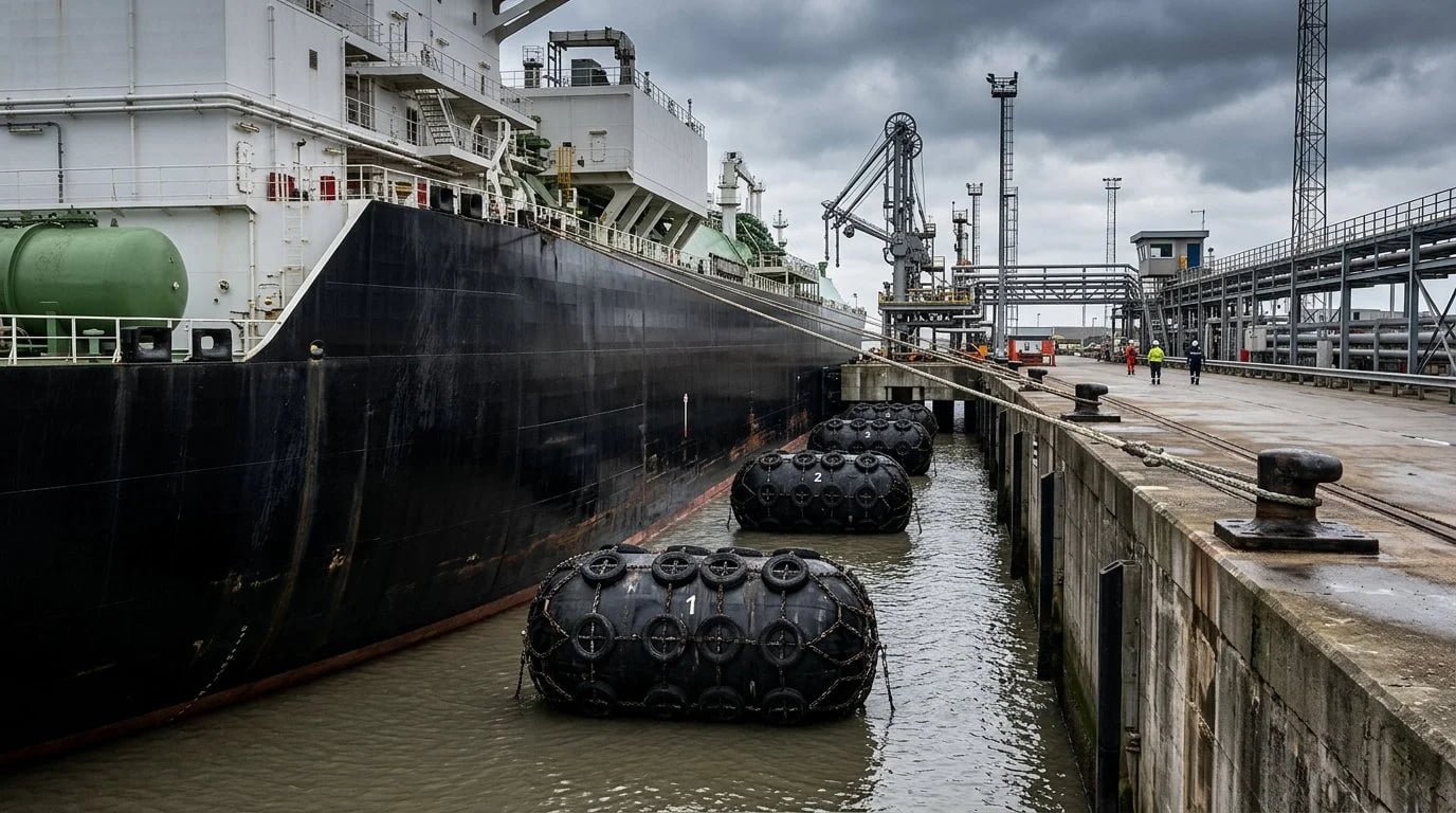
LNG Terminal Fender Design
LNG Terminal Fender System: Design Principles for Port and EPC Engineers
Membrane-hull LNG carriers demand fender systems that keep hull pressure within tight limits. This guide covers berthing load parameters, PIANC WG211 methodology, and pneumatic fender selection for LNG berths.
An LNG terminal fender system is built around large-diameter floating pneumatic fenders, sized by the PIANC WG211 berthing-energy method and constrained by the LNG carrier's allowable hull pressure. Their large, compliant contact area spreads the reaction force and keeps hull pressure within membrane-hull limits, a requirement fixed rubber fenders cannot reliably meet. Fender diameter, length, and initial inflation pressure are selected to match the calculated berthing energy while keeping hull pressure and reaction force within project-specified limits.
Why Pneumatic
The Fender Type LNG Berths Require
Membrane-type LNG carriers place the containment barrier close to the outer shell. That structural reality drives the fender choice.
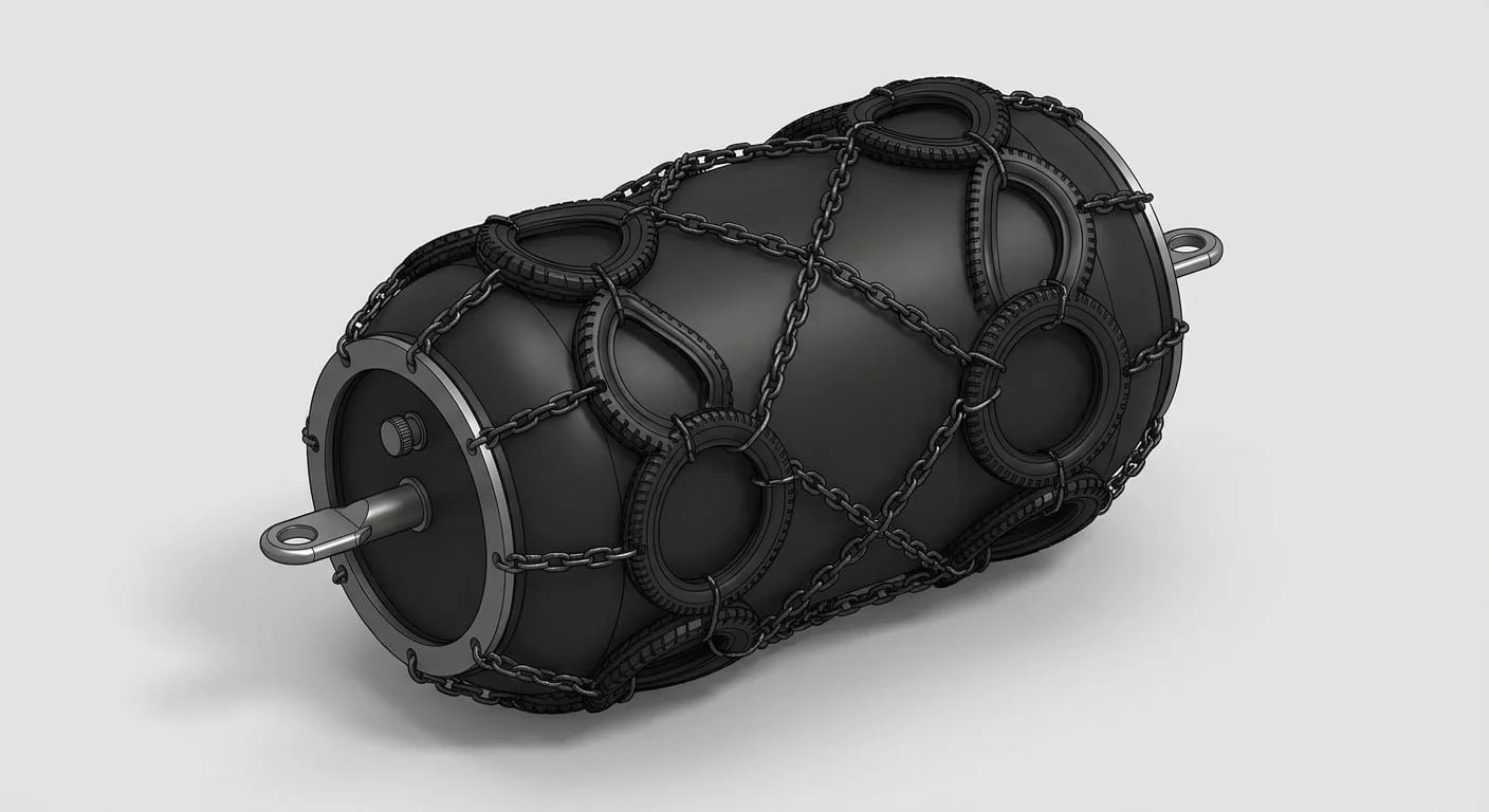
Membrane Hull
Compliant Contact Over Point Loading
Modern LNG carriers (GTT Mark III, NO96) have an inner tank membrane sitting close to the outer shell plating. A fixed cone or cell fender concentrating load on a small contact area creates risk of structural damage that a pneumatic fender's large, compliant contact surface avoids.
Floating pneumatic fenders deform on contact and spread reaction force across a wide hull area, keeping hull pressure within the limits set by the shipbuilder and owner's representative. Fixed fender types remain appropriate for ro-ro, container, and general cargo quays where hull design tolerates higher localized pressure.
Discuss your berth requirement →Design Inputs
Berthing Load Parameters for LNG Terminal Fender Design
Before any fender can be sized, the design berthing energy must be established. It drives fender count, diameter, inflation pressure, and mooring layout.
Approach Velocity
Approach velocity is the most influential variable. Berthing energy scales with the square of velocity, so doubling the speed quadruples the energy. For LNG carriers berthing under tug assistance at established terminals, a normal approach velocity of 0.10-0.15 m/s is commonly referenced in PIANC guidance (confirm per project; abnormal berthing cases and port-specific criteria may apply higher values).
Vessel Displacement and Added Hydrodynamic Mass
Vessel displacement defines the kinetic energy available at a given speed. LNG carriers range from small regional vessels to large Q-Flex and Q-Max class ships. The added hydrodynamic mass, which accounts for the water mass that moves with the vessel during approach, must be included in the energy calculation. Getting this wrong at the parameter stage compounds through every subsequent design decision.
Environmental Factors (Wind, Current, Wave)
Environmental factors set the margin above the normal berthing case. Exposed berths in open roadsteads carry higher wind load at the time of berthing than sheltered basins. Tidal or river currents acting on the broadside of a large LNG hull generate significant transverse force during approach. Swell penetration at offshore or semi-exposed terminals adds a dynamic component captured in the abnormal berthing case.
PIANC WorkCom 211 provides a structured framework for combining these factors into a design berthing energy envelope. The full energy calculation, covering normal and abnormal cases, velocity selection, and added mass coefficients, is covered in our guide to berthing energy calculation for LNG carriers.
The design energy envelope distinguishes a normal case from an abnormal case. The abnormal case multiplies the normal-case energy by a factor from PIANC WG211 Table 4-1, typically 1.25-2.0 depending on berth exposure, to cover tug failure, off-angle approach, or environmental exceedance. The abnormal result is the governing design energy (Ed). LNG carriers must also be assessed in both laden and ballast draft conditions: laden displacement can exceed ballast by 40-50% for a large membrane carrier, directly scaling kinetic energy at the same approach velocity.
Methodology
PIANC Fender Design Methodology
PIANC WG211 structures fender selection as a sequential six-step process. An error at step one propagates through to the final fender choice.
Sequence Matters
A Six-Step Selection Sequence
The sequence runs from vessel parameters through geometry verification. For membrane LNG carriers, hull pressure is often the binding constraint at step five, not raw energy absorption capacity.
The coefficient derivation, exposure classification, and abnormal factor selection are covered in detail in our PIANC WG211 fender design guide.
Get a PIANC-based sizing review →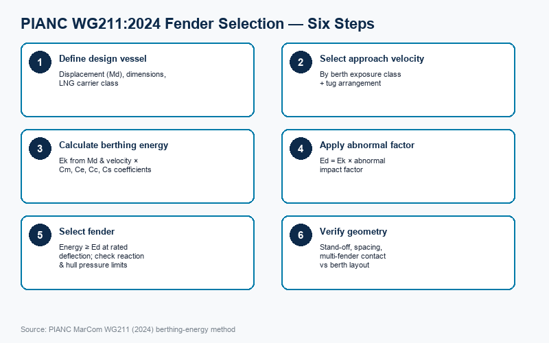
Define Design Vessel and Displacement
Establish vessel class, fully loaded displacement (Md, tonnes), and beam. For mixed-traffic LNG berths, the largest expected vessel governs.
Select Approach Velocity
Based on berth exposure category and tug arrangement. The abnormal berthing case applies a separate, higher velocity, calculated independently.
Calculate Kinetic Energy (Ek)
Apply four correction coefficients: added mass (Cm), eccentricity (Ce), berth configuration (Cc), and softness (Cs). Confirm values per PIANC WG211 and project.
Apply Abnormal Impact Factor
Multiply Ek by the abnormal factor to derive design energy (Ed). This margin covers tug failure, off-angle approach, or environmental exceedance.
Select Fender Type and Size
Rated energy at design deflection must equal or exceed Ed. Verify reaction force does not breach hull pressure limits (kPa). Often hull pressure binds first.
Verify Geometry and Load Sharing
Confirm stand-off distance, gangway clearance, and fender spacing against vessel geometry. Check load distribution against breasting dolphin capacity.
FEED-Stage Support
Working a berth design against a FEED milestone?
Send your design vessel class and berth parameters. We return indicative JYTF sizes with energy and reaction data at 50 kPa and 80 kPa.
Sizing Reference
Recommended Fender Sizes by LNG Carrier Class
Vessel class drives fender sizing. The table maps typical LNG carrier capacity ranges to JYTF starting-point specifications at 50 kPa initial inflation pressure, based on JettyGuard catalog data.
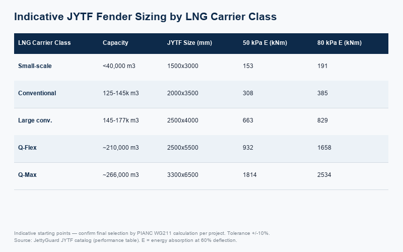
Indicative Only
Starting Points, Not Final Selection
These are indicative starting points, confirm final selection by PIANC calculation per project. Carrier capacity figures are typical membrane-type values; confirm actual displacement (Md) and beam per vessel class.
For projects requiring higher energy absorption at the same diameter, the 80 kPa pressure rating is available for all sizes listed. Hull pressure limits are per project and class, obtain from the vessel owner or classification society before finalising.
Request candidate sizes for your design vessel →| LNG Carrier Class | Typical Capacity | JYTF Size (OD×L mm) | 50 kPa Energy (kNm) | 50 kPa Reaction (kN) | 80 kPa Energy (kNm) | 80 kPa Reaction (kN) |
|---|---|---|---|---|---|---|
| Small-scale LNG | <40,000 m³ | 1500×3000 | 153 | 579 | 191 | 724 |
| Conventional | 125,000-145,000 m³ | 2000×3500 | 308 | 875 | 385 | 1094 |
| Large conventional | 145,000-177,000 m³ | 2500×4000 | 663 | 1380 | 829 | 1725 |
| Q-Flex | ~210,000 m³ | 2500×5500 | 932 | 2010 | 1658 | 2513 |
| Q-Max | ~266,000 m³ | 3300×6500 | 1814 | 3015 | 2534 | 3961 |
Performance tolerance ±10%. Values sourced from the JettyGuard JYTF catalog performance table.
Binding Constraint
Hull Pressure Limits and Why They Matter
Energy absorption is only half the check. On many LNG projects the binding constraint is hull pressure: reaction force divided by the fender-to-hull contact footprint, measured in kPa.
Membrane Containment
Why Diameter, Not Count, Solves It
Membrane-type carriers (GTT Mark III, NO96) carry their primary containment barrier as a thin stainless steel or Invar membrane backed by polyurethane insulation panels close to the inner hull. Localized pressure beyond the allowable limit can crack or delaminate the insulation system, taking the vessel off charter for dockyard repair.
A pneumatic fender's large, compliant contact ellipse distributes the same reaction force over a greater hull area than a fixed rubber cone of equivalent energy rating. Higher diameter means a larger footprint, which means lower pressure at the same reaction force. Increasing diameter, rather than adding more same-size fenders, is often the correct response when hull pressure binds.
Verify hull pressure for your vessel →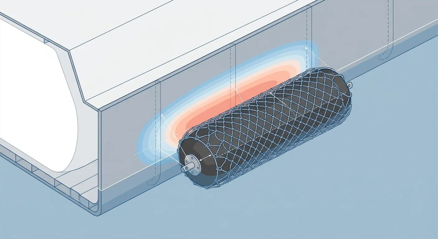
PIANC WG211:2024 Table 6-6 gives a maximum ultimate hull pressure of 200 kN/m² (200 kPa) for gas carriers (LPG and LNG), a value that already incorporates the safety factors normally applied by classification societies. This is a general design guide in the absence of vessel-specific data; the governing limit still depends on the vessel's insulation system generation, structural class, and owner acceptance criteria, and must be confirmed against the applicable class notation and SIGTTO operational guidance for each project.
Hull pressure must be verified in parallel with the energy calculation, not afterward. If a fender passes energy but fails hull pressure, the only correction is a larger diameter, which reruns the energy and reaction force figures from scratch. Catching this early in the design sequence avoids an unnecessary iteration cycle.
Moss spherical-tank vessels are less sensitive to localized hull pressure than membrane types; their self-supporting aluminium spheres carry structural load in a way membrane containment cannot. For membrane vessels, now the majority of the active LNG fleet above 125,000 m³, hull pressure is typically the governing design criterion alongside energy absorption.
PIANC WG211:2024 §6.8 notes that floating pneumatic fenders typically generate a reaction pressure around 170 kN/m², comfortably below the 200 kN/m² ultimate limit for gas carriers. As the fender deforms under load, the contact ellipse grows, preventing reaction pressure from rising proportionally with reaction force. Fixed rubber cone and cell fenders have a smaller, stiffer footprint and offer no equivalent self-spreading mechanism. For LNG terminal fender design, the pneumatic option naturally aligns with the hull pressure constraint without requiring oversize or special hull reinforcement.
Avoid a Late-FEED Redesign
Confirm hull pressure before you commit the spec
Hull pressure iterations require re-running the full energy calculation. We check both in parallel and return sizing that satisfies energy and pressure limits together.
Supplier Evaluation
A Technical Fender Supplier for LNG Projects
For a FEED-stage design basis, the strongest evidence is a fender of the required size with a documented procurement, inspection, and in-service record.
In-Service Reference
The Largest Unit, Already Supplied
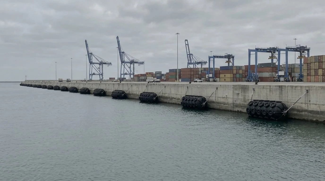
The largest unit in the JYTF range, 4500×9000 mm, has been supplied to an operating LNG ship-to-ship transfer terminal, with pre-shipment inspection conducted by Bureau Veritas.
Client identity and exact terminal location are withheld under commercial confidentiality. Full project documentation, including BV inspection certificate, ISO 17357-1 type test report, and delivery record, is available on request under NDA.
Request the reference documentation →ISO 17357-1:2014 Tested
JYTF pneumatic fenders are manufactured and tested to ISO 17357-1:2014 with full type test documentation. Third-party inspection to Clause 12, covering dimensional check, pull-out test, inflation test, and performance verification, is a standard project deliverable.
Procurement-Ready Records
Type test report, Clause 12 independent inspection report, BV or equivalent pre-shipment certificate, and material traceability certificates (nylon cord, rubber compound, outer tyre net), formatted for direct inclusion in procurement packages.
Full-Spectrum Single Source
The JYTF range runs 500×1000 mm through 4500×9000 mm, covering the full berthing load spectrum from small-scale import terminals to Q-Max carriers. One supplier, one quality documentation set, one technical contact — including the marine rigging gear that completes your fender package.
For a structured comparison of size selection against LNG carrier class and project-specific energy targets, the guide to selecting pneumatic fenders for an LNG terminal covers the sizing methodology in full.
FAQ
Frequently Asked Questions
What fenders are used at LNG terminals?
How are LNG terminal fenders sized?
What is the allowable hull pressure for LNG carriers?
Which standards apply to LNG terminal fender design?
What approach velocity is used for LNG carrier berthing?
Can one supplier cover all fender sizes for an LNG berth?
FEED & Procurement
Submit Your LNG Terminal Fender Inquiry
Submit your design vessel class, containment type, and cargo capacity, and we return candidate fender sizes with energy absorption and reaction force figures at 50 kPa and 80 kPa. Confirming fender parameters early avoids a late-FEED redesign cycle.
What you receive
Indicative JYTF fender sizing, energy and reaction data at two inflation pressures, and a checklist of PIANC WG211 parameters to confirm before committing to a FEED-stage specification.
Required: design vessel class, containment type, cargo capacity, and contact details. All remaining parameters are optional, submit what you have and we work with the gaps.
FEED-Stage Sizing
Candidate JYTF sizes for your design vessel
Energy and reaction data at 50 kPa and 80 kPa, plus a PIANC WG211 parameter checklist.
Request a Review