
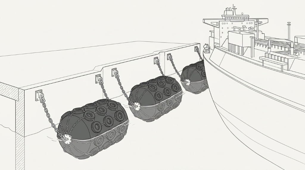
How do you calculate berthing energy for an LNG carrier? A berthing energy calculation follows PIANC MarCom 211 (2024): Ek = (½ × M × V²) × Ce × Cm. M is laden displacement, V is berthing velocity, Ce is the eccentricity factor, and Cm is the added mass factor. A partial energy factor (γE) is then applied to get the design energy, which sets the minimum fender energy absorption.
LNG carriers are large, expensive, and sensitive to side-shell loads. A berth that is fine for a Panamax bulker can be wrong for a 174,000 m³ LNG carrier. The berthing energy a fender system must absorb scales with vessel mass and the square of berthing velocity, so small changes in approach speed produce large changes in energy. This guide walks through the calculation that turns vessel particulars into a fender size.
The basic workflow has six steps:
- Confirm the design vessel and laden displacement (M, in tonnes).
- Select berthing velocity (V) from PIANC MarCom 211 by exposure class.
- Determine the added mass factor (Cm) from hull form and under-keel clearance.
- Apply the eccentricity factor (Ce) for the contact point.
- Compute the characteristic kinetic energy Ek in kNm.
- Apply the partial energy factor (γE) and select a fender from the ISO 17357 catalogue.
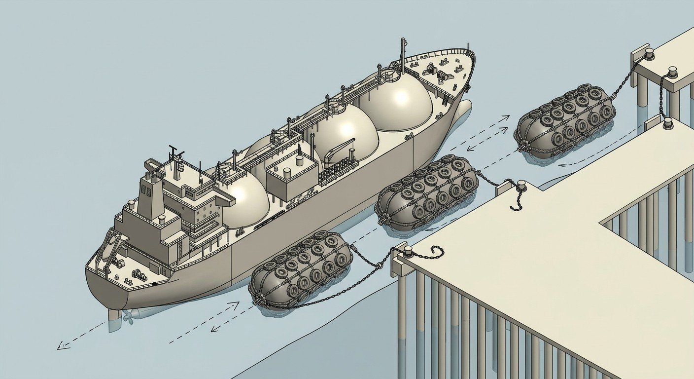
What Is Berthing Energy and Why It Matters for LNG Carriers
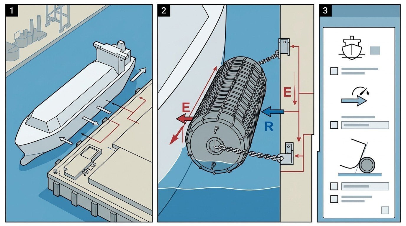
Berthing energy is the kinetic energy a vessel transfers to a fender system at the moment of contact with a berth. The fender deforms, absorbs that energy, and limits the reaction force pushed back into the hull and the structure. If the fender is undersized, either the hull plating sees too much pressure or the quay structure takes loads it was not designed for.
For an LNG carrier the consequences of a wrong fender size are not just structural. A damaged cargo containment system or a fender failure during cargo transfer creates a safety event that stops the terminal. This is why LNG and FSRU projects size fenders against PIANC MarCom 211 (2024) and the SIGTTO guidance instead of generic port codes.
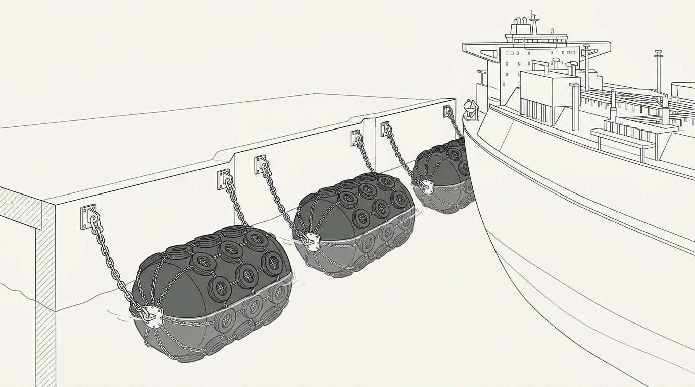
The Berthing Energy Formula (PIANC MarCom 211)
The kinetic energy form used in PIANC MarCom 211 (2024) is:
Ek = (½ × M × V²) × Ce × Cm
Where:
- Ek = characteristic berthing energy (kNm)
- M = laden displacement of the vessel (tonnes)
- V = berthing velocity normal to the berth (m/s)
- Ce = eccentricity factor
- Cm = added mass factor
WG211 (2024) uses only Ce and Cm. The earlier WG33 (2002) formula also carried a softness factor (Cs) and a berth configuration factor (Cc); WG211 removed both. Cs was dropped because the elastic contribution of the hull is below 1%, and Cc because its effect is already captured in the recorded berthing velocities.
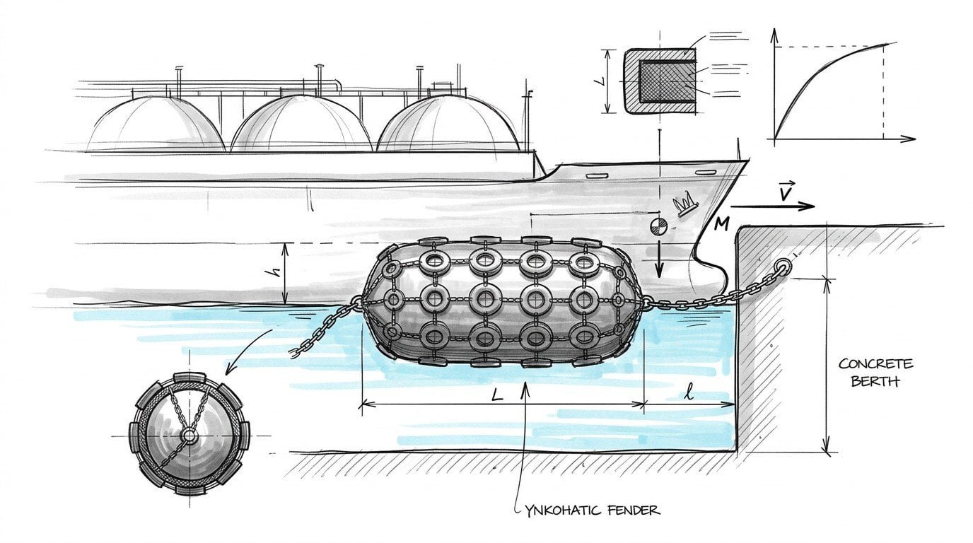
The formula gives the characteristic kinetic energy at the contact point, not the gross kinetic energy of the vessel. Ce and Cm translate ship-side physics into the energy a single fender or fender group must absorb. The fender selected then needs a rated energy at design deflection that meets or exceeds the design energy Ek,d, which is Ek multiplied by the partial energy factor γE (Section 5.8 of WG211).
A common mistake is to assume Ce = 1.0 because “the ship comes in flat.” On real berths, Ce alone can change the result by a factor of two.
Key Parameters in LNG Carrier Berthing Energy Calculation
The four inputs to the formula deserve a closer look. For an LNG carrier the value ranges are tighter than for general cargo vessels.
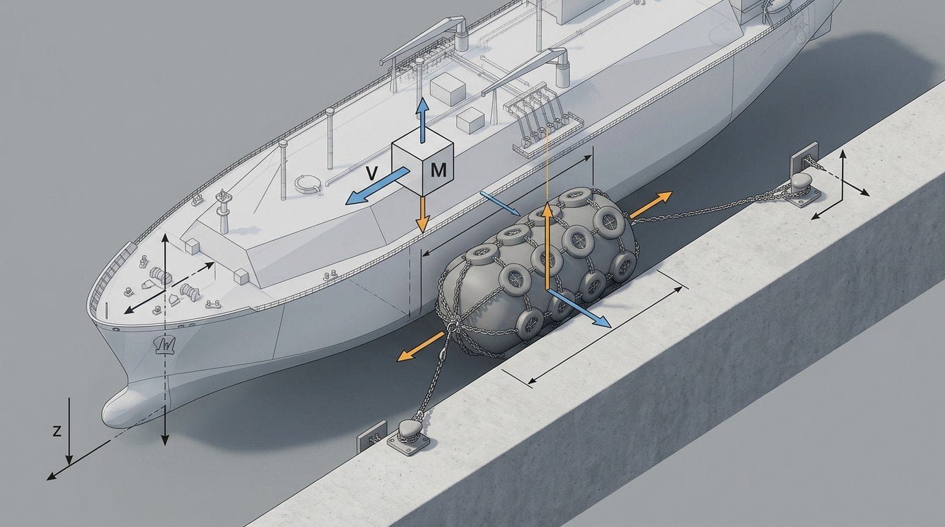
Vessel Displacement (M)
Use laden displacement, not deadweight. For a 174,000 m³ large conventional LNG carrier the laden displacement is around 125,000 tonnes. A Q-Flex (around 210,000 m³) sits closer to 150,000 tonnes, and a Q-Max (266,000 m³) closer to 175,000 tonnes. Conventional 138,000–155,000 m³ carriers fall around 95,000–115,000 tonnes laden. Always confirm M from the vessel particulars, not from a class rule of thumb.
Berthing Velocity (V)
Berthing velocity is the most sensitive input because it is squared. PIANC MarCom 211 publishes characteristic velocities by navigation condition (favourable, moderate, unfavourable) and vessel size. For the largest LNG carriers in favourable to moderate conditions with tug assistance, design V is usually 0.10–0.15 m/s. Unfavourable conditions or restricted tug support can push V to 0.25 m/s.
Added Mass Coefficient (Cm)
Cm accounts for the water moving with the hull. PIANC MarCom 211 sets Cm mainly from the under-keel clearance: at low clearance (under-keel clearance below ~10% of draft) Cm reaches about 1.8, and at deep water (clearance above one draft) it drops toward 1.5. For LNG carriers the working range is roughly 1.4 to 1.8. Treating Cm as a fixed 1.5 without checking the under-keel clearance is a common error.
Eccentricity Factor (Ce)
Ce captures the rotation of the vessel about the contact point during berthing. For a midship contact Ce is 1.0; for a quarter-point contact it drops to about 0.5. Most real LNG berthings are between these two values, and Ce is often the difference between the right fender size and a wrong one.
Softness and Berth Configuration Factors (Cs, Cc) — Removed in WG211
If you are working from an older spec, you will see two more factors. The softness factor (Cs) and the berth configuration factor (Cc) were part of the WG33 (2002) formula. WG211 (2024) removed both, so do not apply them when you cite the current standard. Cs went because the hull’s elastic contribution is under 1%; Cc went because its effect is already inside the recorded berthing velocities. For ship-to-ship and FSRU side-by-side berthing, follow SIGTTO guidance rather than reaching back for the old factors.
Worked Example: 174,000 m³ Large Conventional LNG Carrier
This is a simplified example, not an engineering deliverable. The point is to show the numbers travelling through the formula end to end.
| Parameter | Symbol | Value | Source |
|---|---|---|---|
| Laden displacement | M | 125,000 t | Vessel particulars |
| Berthing velocity | V | 0.12 m/s | PIANC MarCom 211, favourable–moderate |
| Eccentricity factor | Ce | 0.5 | Quarter-point contact |
| Added mass factor | Cm | 1.5 | Conventional LNG hull, deep water |
Substituting:
Ek = (½ × 125,000 × 0.12²) × 0.5 × 1.5
Ek ≈ 675 kNm
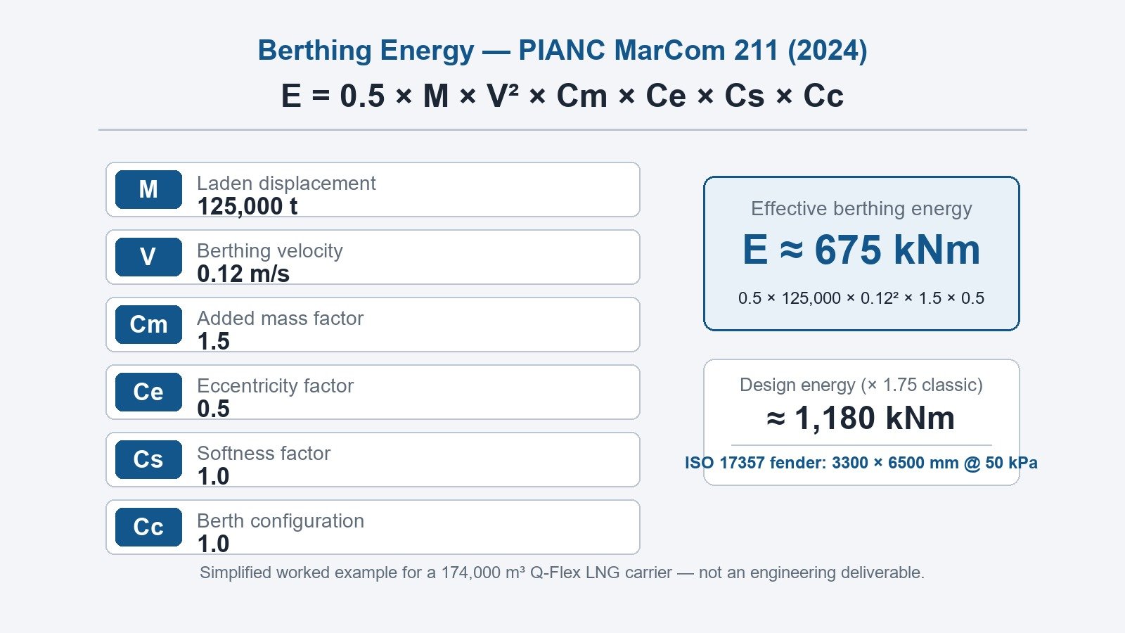
So the characteristic berthing energy is about 675 kNm. Applying a partial energy factor of about 1.75 gives a design energy of around 1,180 kNm. From the ISO 17357-1:2014 catalogue this maps to a 3300 × 6500 mm Yokohama-type pneumatic fender at 50 kPa initial internal pressure (IIP), with a guaranteed energy absorption of 1,814 kNm and reaction force of 3,015 kN. The reaction force and hull pressure check then decide whether you hold at that size or move up.
One note on the factor. The single “abnormal factor 1.5–2.0” is the WG33 (2002) approach. PIANC MarCom 211 (2024) replaces it with a partial energy factor selected by consequence class and navigation condition (for a class B berth in moderate conditions the reference value is about 1.55–1.65, per Table 5-8). Use the ×1.75 here as a quick pre-size only.
The number is realistic but the inputs are simplified. A real project review will revisit V, Cm, and Ce against the actual berth, the tug plan, and the design vessel envelope. Treat 675 kNm as a starting point, not a specification.
From Berthing Energy to Fender Size: Linking E to ISO 17357 Sizing
Once Ek is known, fender selection is bounded by three checks:
- Rated energy at design deflection ≥ Ek × partial energy factor (γE).
- Reaction force at design deflection ≤ allowable hull pressure × contact area.
- Hull pressure ≤ vessel-specific limit (PIANC gives 200 kPa as the limit for gas carriers).
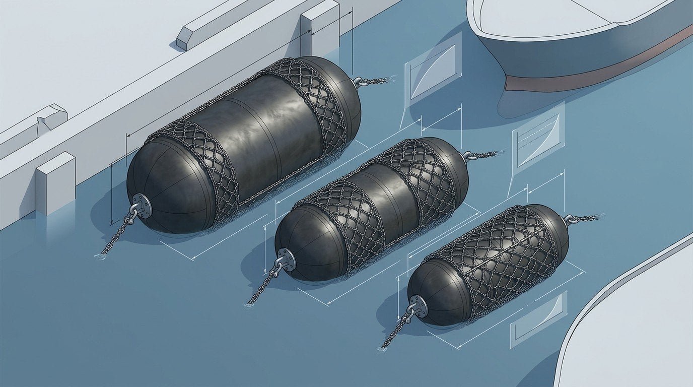
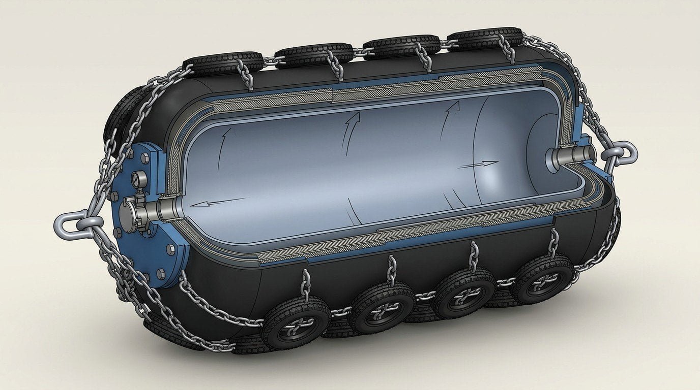
ISO 17357-1:2014 lists rated energy and reaction force for each pneumatic fender size at standard internal pressures of 50 kPa and 80 kPa. The energy value sets the minimum fender; the reaction force and hull pressure check sets whether you stay at that size or move up to spread the load. For FSRU side-by-side and STS work, follow the fender count for FSRU berthing under SIGTTO before locking the size.
For the full size table see the ISO 17357 pneumatic fender size chart, and for the project workflow see the five-step pneumatic fender selection process for LNG terminals.
Standards and References
These are the documents an LNG terminal fender package is reviewed against:
- PIANC MarCom WG 211 (2024) — Guidelines for the Design, Manufacturing and Testing of Fender Systems. The current reference for the formula, velocity data, and factors. It completely supersedes WG33 (2002).
- ISO 17357-1:2014 — Ships and marine technology — Floating pneumatic rubber fenders — Part 1: High pressure. Defines rated energy, reaction force, and test methods.
- OCIMF MEG4 — Mooring Equipment Guidelines, 4th Edition. Used for review of mooring and berthing arrangements at LNG terminals.
- SIGTTO — guidance for LNG operations in port areas and ship-to-ship transfer. The reference for ship-to-ship and FSRU side-by-side fender plans.
- BS 6349-4:2026 — Maritime works, Part 4: Code of practice for design of fendering and mooring systems. A regional alternative used in UK and Commonwealth projects.
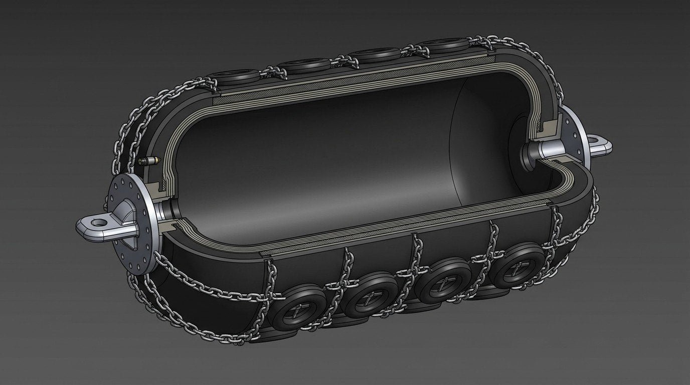
For ISO compliance details on Yokohama-type pneumatic fenders, see the ISO 17357-1:2014 requirements page.
What Data to Send JettyGuard for a Berthing-Energy Review
When a customer asks JettyGuard for a fender selection or sizing analysis, the inputs below are the ones that drive the result. Missing inputs force assumptions, and assumptions are where size errors come from.
| Data point | Unit | Why it matters |
|---|---|---|
| Vessel class / cargo capacity | m³ | Maps to displacement |
| Laden displacement | tonnes | M in formula |
| LOA, beam, draft | m | Hull form, pressure check |
| Berth exposure class | sheltered / semi-exposed / exposed | Drives V |
| Berthing approach angle | degrees | Drives Ce |
| Berth type | open jetty / closed quay / FSRU side-by-side | Affects velocity and approach |
| Tug assistance | yes / no, bollard pull | Sanity-checks V |
| Hull pressure limit | kPa | Constrains fender size |
| Existing fender plan | drawing / spec | For replacement projects |
JettyGuard usually returns a fender selection and sizing analysis report that defines the working fender size and quantity for the project. The number gets misread often. Customers take the report quantity as the exact purchase quantity: if it says three working fenders, they buy three, and the spares get dropped to trim the budget.
I worked with a Middle East STS operator who did exactly this. The sizing report listed working fenders plus one spare; they ordered only the working set to save cost. Months later one fender failed on site, and a matching 3300 × 6500 replacement was weeks away. The transfer window slipped while they waited.
That trade rarely pays off. Even good pneumatic fenders have a small failure probability, and STS and LNG transfer are already high-cost, high-risk operations. A missing spare can stop the operation and add safety exposure far more expensive than the spare itself.
Common Errors in LNG Berthing Energy Calculation
The six errors below show up most often in fender packages we are asked to review:
- Using bulk-carrier velocity tables instead of LNG-class values from PIANC MarCom 211.
- Treating Cm as a fixed 1.5 without checking the actual under-keel clearance.
- Setting Ce = 1.0 by assuming midship contact, which rarely matches a real berthing.
- Confusing rated energy at 60% deflection with energy at design deflection.
- Still applying the WG33 abnormal berthing factor instead of the WG211 partial energy factor (γE).
- Treating FSRU side-by-side berthing the same as fixed-quay LNG carrier berthing.
Any one of these can move the required fender energy by 30–100%. Two of them stacked usually mean the wrong fender on site.
Frequently Asked Questions
What is berthing energy?
Berthing energy is the kinetic energy a vessel transfers to a fender at the moment of contact with a berth. The fender absorbs that energy by deforming. Berthing energy in kNm is the input that determines the minimum fender size for a project.
How is berthing energy different from kinetic energy?
Gross kinetic energy is ½ × M × V². Characteristic berthing energy multiplies it by two PIANC WG211 factors, Ce (eccentricity) and Cm (added mass), so the fender only sees a fraction of the gross figure. The design energy then adds a partial energy factor (γE) for safety.
What berthing velocity should I use for an LNG carrier?
Use PIANC MarCom 211 (2024) by navigation condition. For favourable to moderate conditions with full tug assistance, V is typically 0.10–0.15 m/s. Unfavourable conditions or limited tug support can push V to 0.25 m/s. Confirm the value with the project marine consultant.
Does this calculation replace a full mooring or berthing study?
No. This article is a methodology overview. A real LNG project requires a project-specific dynamic mooring analysis (DMA) and a berthing study by a qualified naval architect or marine engineer. The formula here is for understanding and pre-sizing, not for sign-off.
Engineering Disclaimer and Next Step
This article is a methodology guide. It does not replace a project-specific berthing study, dynamic mooring analysis, or the engineering review carried out by a qualified naval architect or marine engineer. Use it to scope the calculation and the data package, not to size the final fender package.
Send the data table above to JettyGuard and we will return a sizing review with Yokohama-type pneumatic fenders mapped to your design vessel and berth. For the project workflow, see the pneumatic fender selection process for LNG terminals.