
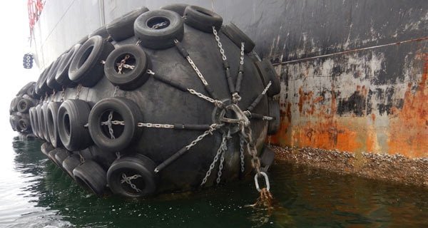
Select a pneumatic fender for an LNG terminal in five steps: calculate effective berthing energy using vessel displacement and PIANC MarCom 211 velocity tables, match energy absorption to an ISO 17357-1:2014 standard fender size, verify hull pressure stays within the vessel’s allowable limit, confirm OCIMF and SIGTTO guidance is met, and obtain BV, DNV, or ABS certification records.
LNG infrastructure is not a general cargo berth. A fender failure during LNG carrier berthing is a safety event, not a maintenance issue. The selection process for pneumatic fenders for FSRU and LNG terminals is more constrained than most marine applications: hull pressure limits are tighter, standards compliance is mandatory, and undersizing has serious consequences. You need to work through five steps in order.
To select a pneumatic fender for an LNG terminal:
- Define berthing energy (vessel displacement and approach speed)
- Match fender size to the ISO 17357-1:2014 energy absorption table
- Check hull pressure limits for LNG carriers (PIANC gas carrier limit ~200 kN/m²)
- Confirm OCIMF and SIGTTO guidance requirements
- Review certification and inspection records (BV / DNV / ABS / LR)
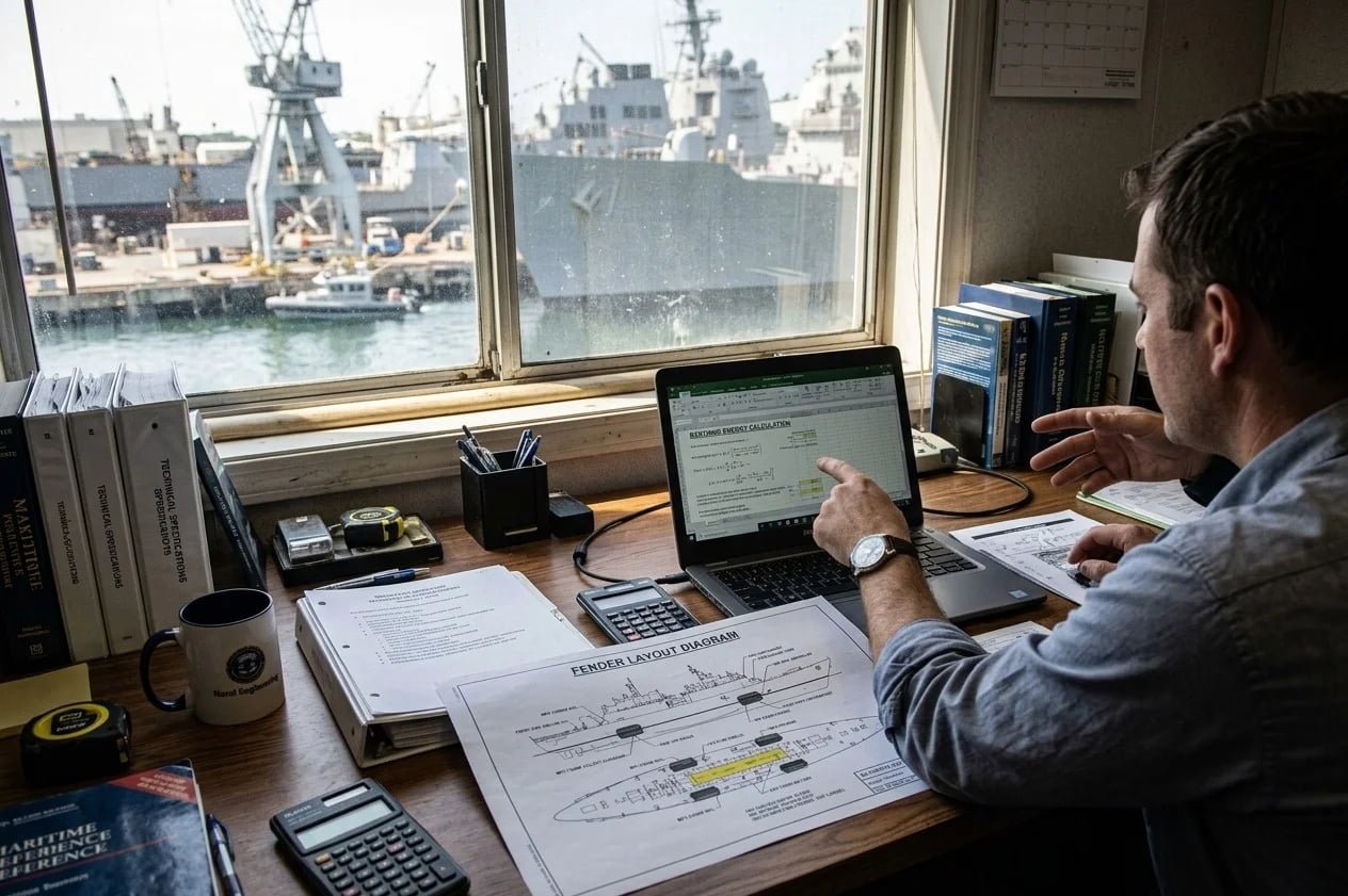
Step 1: Define Berthing Energy (Vessel DWT and Approach Speed)
Start with the effective kinetic energy the fender must absorb. This is not the vessel’s full kinetic energy. It is the fraction that reaches the fender after accounting for hull geometry and contact conditions.
The formula:
E = 0.5 × M × V² × Cm × Ce
M is vessel displacement in tonnes. V is berthing velocity in m/s. Cm is the added mass coefficient. Ce is the eccentricity factor.
Worked example — 145,000 m³ Q-Flex LNG carrier:
- Displacement: approximately 120,000 tonnes (fully laden)
- Berthing velocity: 0.15 m/s — PIANC MarCom Report No. 211 (2024), sheltered berth, good conditions
- Cm = 1.5 (typical for LNG carrier hull form)
- Ce = 0.5 (typical for parallel body contact)
E = 0.5 × 120,000 × (0.15)² × 1.5 × 0.5 = 1,012 kNm
This maps to a 3000 × 6000 mm fender at 50 kPa initial inflation pressure (IIP). That size has a rated energy absorption of approximately 1,050 kNm under ISO 17357-1:2014. The 50 kPa IIP is standard for LNG terminal applications.
One important note on FSRU projects: PIANC MarCom 211 (2024) supersedes the earlier PIANC 2002 Guidelines for the Design of Fender Systems for LNG applications. The 2024 edition has updated velocity tables that separate fixed terminal berthing from FSRU alongside operations. FSRU berthing involves two floating hulls. The approach dynamics are different. Quay berthing velocity tables do not apply directly. For more on fender sizing parameters, see our pneumatic fender specifications page.
Step 2: Match Fender Size to the ISO 17357-1:2014 Energy Absorption Table
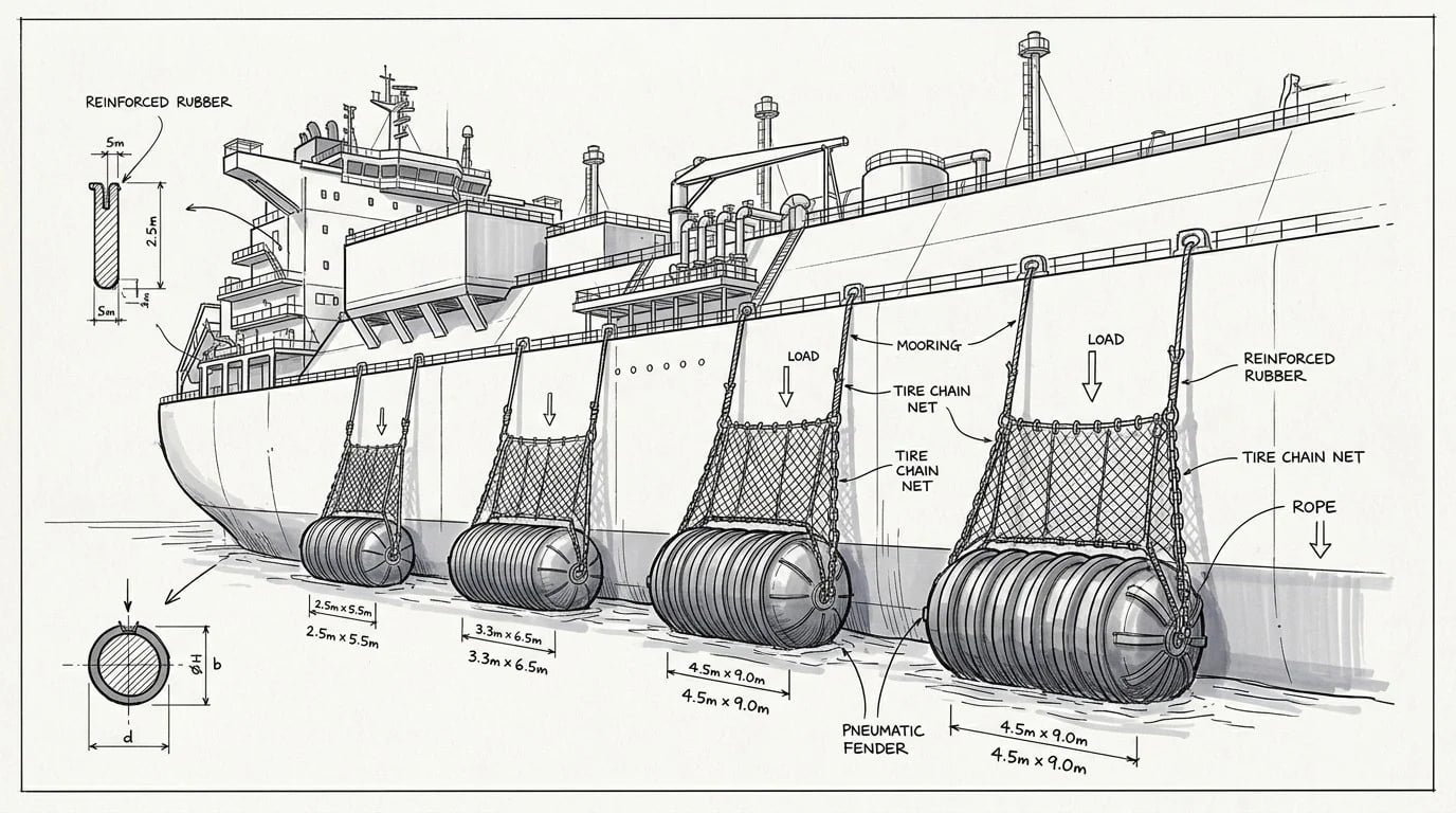
ISO 17357-1:2014 specifies each fender by construction type (Type I net-type, Type II sling-type) and initial internal pressure (Pneumatic 50 at 50 kPa, Pneumatic 80 at 80 kPa). For every nominal size it publishes a guaranteed energy absorption (GEA), reaction force, and hull pressure value at 60% deflection. Selection starts from that table: find the size whose GEA meets your design energy at the pressure grade you need.
What matters for LNG procurement is the testing and certification scope behind those values. The standard defines two separate tests: the Clause 8 prototype test, run once per basic design and re-validated every ten years by a major classification society, which confirms the design meets its GEA; and the Clause 9 test and inspection for commercial fenders, the per-order acceptance testing and dimensional inspection of the fenders you actually receive. For LNG terminals, specify both — the Clause 8 prototype certificate plus Clause 9 commercial acceptance testing, with Clause 12 independent third-party inspection where required.
Apply a safety factor of 1.5 to 2.0 to the calculated effective berthing energy before selecting fender size. For the 1,012 kNm example above, a safety factor of 1.5 gives a design energy of approximately 1,520 kNm — which maps to the 3300 × 6500 mm size.
Standard pneumatic fender sizes for LNG terminal applications (ISO 17357-1:2014, 50 kPa IIP):
| Size (D × L mm) | Energy Absorption (kNm) | Reaction Force (kN) | Hull Pressure (kPa) | Typical Application |
|---|---|---|---|---|
| 2500 × 5500 | 610 | 1,150 | 190 | Panamax LNG, STS |
| 3000 × 6000 | 1,050 | 1,580 | 210 | Q-Flex LNG carrier |
| 3300 × 6500 | 1,420 | 1,920 | 215 | Q-Max LNG carrier |
| 3500 × 7000 | 1,780 | 2,210 | 218 | VLCC / large FSRU |
| 4000 × 8000 | 2,650 | 2,980 | 220 | Ultra-large FSRU |
For the full size table and selection tool, see pneumatic fenders for FSRU and LNG terminals.
The hull pressure column matters here. When comparing pneumatic fender vs foam fender for LNG applications, this is the deciding factor. Foam fenders generate higher reaction forces for equivalent energy absorption. At LNG carrier scale, keeping hull pressure within the gas-carrier limit is harder. Hull pressure values above are indicative — confirm the final figure against the manufacturer’s certified performance curve and the vessel’s allowable hull pressure (see Step 3).
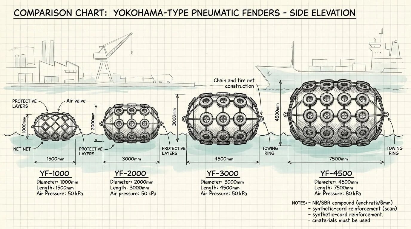
Step 3: Check Hull Pressure Limits for LNG Carriers
Hull pressure is reaction force divided by the contact area between the fender and the hull. Most buyers underweight this constraint. It is the one that causes the most problems when it is wrong.
LNG carrier hulls are thin steel, built to carry cryogenic cargo — not to absorb concentrated berthing loads. PIANC WG211 (2024) Table 6-6 gives a maximum ultimate hull pressure of 200 kN/m² for gas carriers (LNG/LPG) — lower than the values allowed for large tankers and bulk carriers. Typical design reaction pressures sit around 170 kN/m², with extra-soft arrangements as low as 110 kN/m².
Any fender selection that pushes hull pressure above the vessel’s allowable limit is not acceptable — regardless of whether the energy absorption number is sufficient. Always confirm the figure against the specific vessel’s stated allowable hull pressure.
If the fender size needed to absorb the design energy produces hull pressure above the allowable limit, the correct response is to add more fenders per side. Distribute the load. Do not select a smaller fender that cannot absorb the energy.
Hull pressure calculation: P = F / A. F is the reaction force from the fender performance curve. A is the contact area. For a cylindrical pneumatic fender, contact area is approximately 0.4 × D × L at full deflection. Use the manufacturer’s certified performance curve, not a generic estimate.
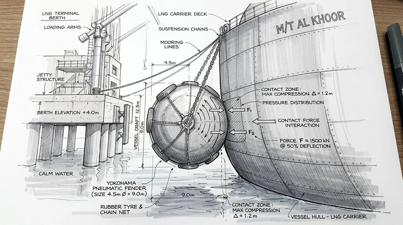
Step 4: Confirm OCIMF and SIGTTO Compliance Requirements
Two industry bodies define the compliance framework for LNG fender operations. Neither certifies fenders directly. They define what documentation and operational practice the terminal operator and vessel owner must maintain.
The OCIMF Ship-to-Ship Transfer Guide is the governing reference for STS fender selection and berthing energy. Its Appendix H covers the fender selection calculation and the size and energy tables. The guide sets out the energy envelope and fender positioning in the parallel body zone; it does not name specific fender sizes.
SIGTTO FSRU Mooring and Fender Guidelines adds FSRU-specific requirements. An FSRU is a floating structure. The fender system must account for relative motion between two hulls under tidal and current loading. SIGTTO specifies fender positioning, the number of fenders per side, and the operational conditions under which berthing is permitted.
A compliant specification clause for LNG terminal fender procurement should state: ISO 17357-1:2014, Clause 9 commercial fender test and inspection certificate per unit (with a valid Clause 8 prototype test certificate on the design), energy absorption and reaction force at 50 kPa IIP, hull pressure within the vessel’s allowable limit, and alignment with the OCIMF Ship-to-Ship Transfer Guide and SIGTTO FSRU Mooring and Fender Guidelines where applicable.
One thing worth clarifying: OCIMF does not issue fender certificates. When a buyer asks for “OCIMF-certified fenders,” what they actually need is a fender that meets the performance envelope in the OCIMF STS Transfer Guide, supplied with ISO 17357-1:2014 Clause 8 prototype and Clause 9 commercial test certificates from a recognized third-party body.
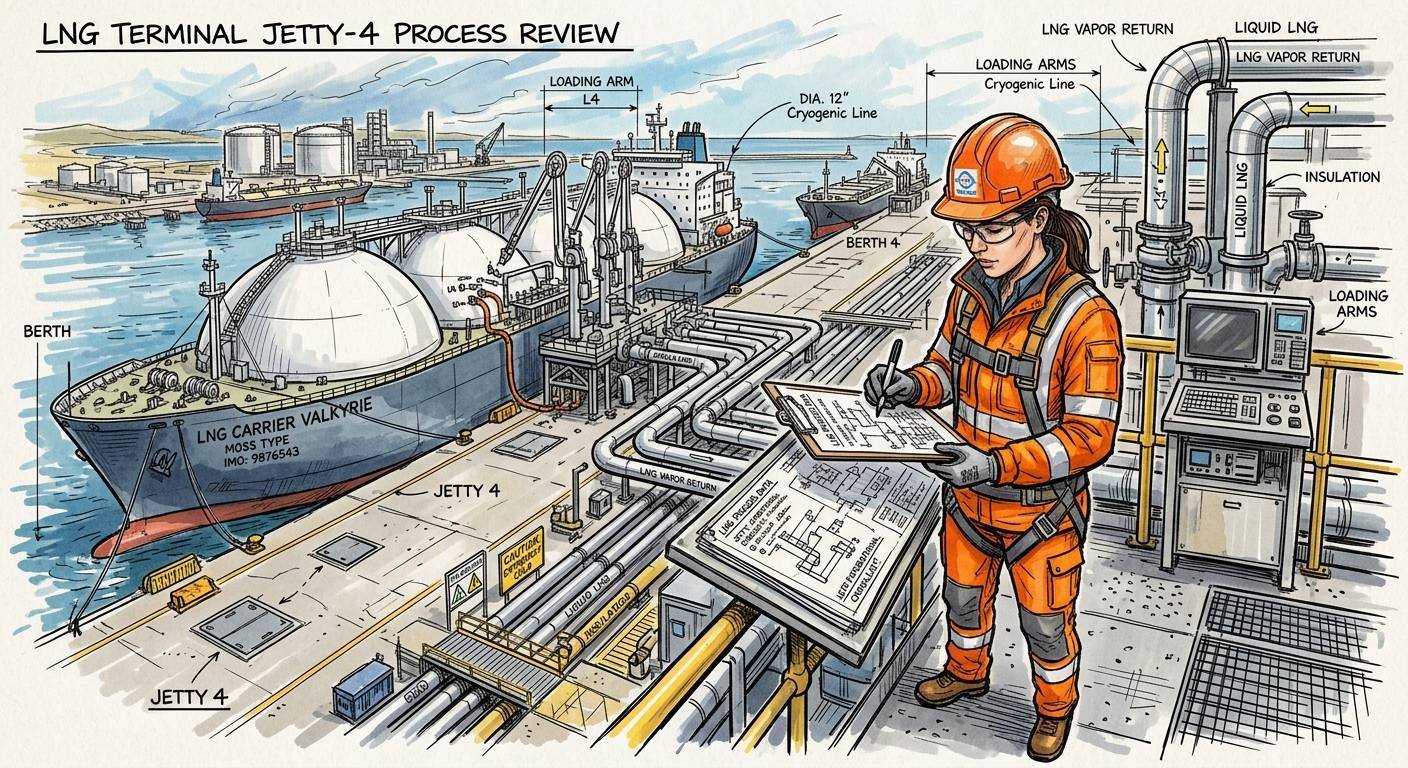
Step 5: Review Certification and Inspection Records (BV / DNV / ABS)
Third-party certification covers three areas: material testing, dimensional verification, and performance testing. The certificate confirms that the fender was made from materials meeting the specification, that dimensions are within tolerance, and that the fender was inflated and tested to the rated pressure and energy absorption values.
Accepted certification bodies for LNG terminal applications are Bureau Veritas (BV), Det Norske Veritas (DNV), American Bureau of Shipping (ABS), and Lloyd’s Register (LR). All four are recognized by major LNG operators and classification societies.
Before accepting delivery, request the following for each fender unit:
- Clause 9 commercial fender test and inspection certificate — confirms the specific unit was acceptance-tested and dimensionally inspected
- Clause 8 prototype test certificate for the design — confirms the design’s guaranteed energy absorption, evaluated by a major classification society
- Material test reports for the rubber compound and cord reinforcement
- Dimensional inspection report (diameter, length, wall thickness)
- Pressure test record (inflation to rated IIP, hold time, pressure drop measurement)
- Net and sling hardware inspection record (for Type I net-type fenders)
The certificate should state the fender serial number, test date, test pressure, energy absorption result, and reaction force result. The Clause 8 prototype certificate proves the design meets its rated GEA; the Clause 9 certificate proves the specific units delivered were tested and inspected. Ask for both — a prototype certificate alone does not confirm the units you receive were individually inspected.
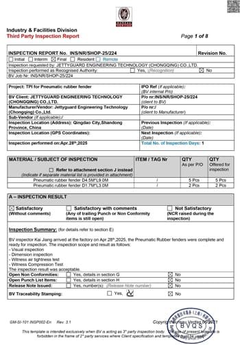
Common Selection Errors and How to Avoid Them
Error 1: Using quay berthing velocity tables for FSRU projects.
PIANC MarCom 211 (2024) provides separate velocity tables for fixed terminal berthing and floating structure operations. FSRU berthing involves two floating hulls with independent motion responses. Using the quay berthing velocity — which assumes a fixed structure — underestimates the effective approach energy. The result is an undersized fender. Always identify whether the project is a fixed terminal or FSRU before selecting the velocity input.
Error 2: Specifying ISO 17357 without stating the test and inspection scope.
A specification that reads only “ISO 17357 pneumatic fender” leaves the acceptance-testing scope open. Without naming it, a supplier can deliver against a prototype certificate alone, with no per-order acceptance testing on the units you receive. For LNG terminals, write “ISO 17357-1:2014, Clause 8 prototype test certificate plus Clause 9 commercial fender test and inspection per unit, Clause 12 independent inspection where required” in the specification.
Error 3: Ignoring hull pressure limits for LNG carriers.
I’ve seen buyers select fender size based on energy absorption alone, then find out during engineering review that the reaction force produces hull pressure above the vessel’s allowable limit. At that point, the fender order is already placed. The correction — adding fenders per side or changing size — delays the project. Check hull pressure against the vessel’s allowable limit (PIANC WG211 gives ~200 kN/m² for gas carriers) before finalizing the size selection.
Error 4: Selecting fender size from energy absorption alone without checking reaction force.
Energy absorption and reaction force are both outputs of the fender performance curve. A larger fender absorbs more energy but also generates more reaction force. The correct selection satisfies both the energy absorption requirement and the hull pressure constraint at the same time. Use the full performance table, not just the energy column.
Error 5: Cost-only procurement on LNG infrastructure.
This is the error I see most often. It is also the most expensive one over the project lifecycle.
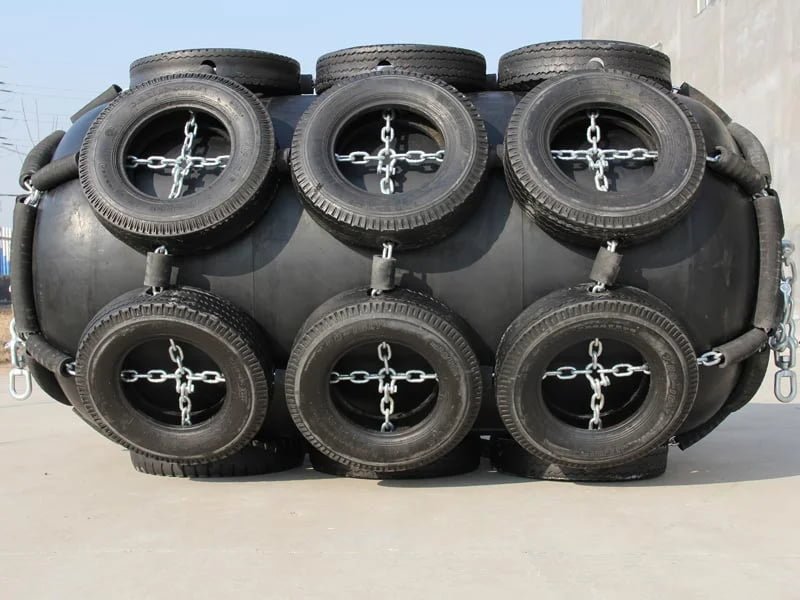
In the Chinese manufacturing market, pneumatic fenders are produced by two fundamentally different processes. Manual wrapped fenders are built by hand-wrapping rubber and cord layers around a mandrel. Quality depends on the skill of the individual worker, the consistency of the rubber compound, the number of reinforcement layers, and the factory’s process control. Prices vary enormously across suppliers — and that variation reflects real differences in material quality, layer count, and workmanship.
Mold-type fenders are manufactured in a closed mold under controlled pressure and temperature. The geometry is consistent. The rubber compound is uniform. The reinforcement layers are positioned precisely. The result is a fender with predictable performance and a service life that manual wrapped products at equivalent price points cannot match.
I’ve seen buyers at LNG infrastructure projects select manual wrapped fenders from the lowest-price tier. The logic is straightforward: the specification says ISO 17357, the supplier provides a certificate, the price is attractive. What the buyer cannot verify at purchase is service life. A manual wrapped fender from a low-unit-price supplier may last three to five years under regular LNG terminal operating conditions. A mold-type fender from a quality manufacturer will last 15 years or more.
Mold-type fenders cost approximately 30% more than manual wrapped products from Chinese peers. That premium buys roughly double the service life. On an LNG terminal with a 20-year operating horizon, the lifecycle cost of the lower-price option is higher — not lower.
Major international brands supply mold-type fenders at prices that reflect their brand premium, certification overhead, and distribution costs. JettyGuard mold-type fenders are manufactured to the same process standard and deliver equivalent service life, at below 50% of major international brand pricing. For LNG infrastructure, mold-type is the correct specification. The question is which mold-type supplier fits your project budget.
Frequently Asked Questions
What is the minimum energy absorption for a pneumatic fender at an LNG terminal?
There is no single minimum that applies to all LNG terminals. The required energy absorption depends on the vessel class berthing at that terminal. For a Panamax LNG carrier (approximately 60,000–80,000 tonnes displacement) at a sheltered berth, effective berthing energy typically falls in the 400–700 kNm range, which maps to a 2500 × 5500 mm fender at 50 kPa IIP. For Q-Flex and Q-Max class carriers, the range is 800–1,500 kNm. Always calculate from the specific vessel displacement and PIANC MarCom 211 (2024) velocity tables rather than using a generic minimum.
What hull pressure limit applies to LNG carriers?
PIANC WG211 (2024) Table 6-6 gives a maximum ultimate hull pressure of 200 kN/m² for gas carriers (LNG/LPG) — lower than the values allowed for large tankers and bulk carriers. Typical design reaction pressures are around 170 kN/m². LNG carrier hulls are thin steel designed for cryogenic cargo containment, not for absorbing concentrated berthing loads. Any fender selection that produces hull pressure above the vessel’s allowable limit at the design berthing energy is not acceptable, regardless of whether the energy absorption figure is sufficient. Always confirm against the specific vessel’s stated allowable hull pressure.
What test certificates does ISO 17357-1:2014 require for LNG terminal fenders?
ISO 17357-1:2014 defines two tests, and an LNG terminal specification should call for both. The Clause 8 prototype test validates a design’s guaranteed energy absorption — it is evaluated by a major classification society and re-validated every ten years. The Clause 9 test and inspection for commercial fenders is the per-order acceptance testing and dimensional inspection of the units you actually receive. Add Clause 12 independent third-party inspection where required. Write “ISO 17357-1:2014, Clause 8 prototype certificate plus Clause 9 commercial fender test and inspection per unit” in your specification.
Can the same fender size be used for both FSRU berthing and fixed terminal berthing?
The same physical fender size can be used in both applications, but the selection calculation must be run separately for each. FSRU berthing uses different berthing velocity assumptions than fixed terminal berthing — PIANC MarCom 211 (2024) provides separate tables for each case. An FSRU project may need a larger fender than a fixed terminal handling the same vessel class, because relative motion between two floating hulls produces different effective energy inputs. Do not transfer a fender size from a fixed terminal specification to an FSRU project without recalculating.
Specifying pneumatic fenders for an LNG terminal or FSRU project? Send JettyGuard your vessel class, displacement, and berthing conditions for a free size recommendation. See our full range and technical data at pneumatic fenders for FSRU and LNG terminals. For the complete system-level design framework, see our guide to the LNG terminal fender system.