
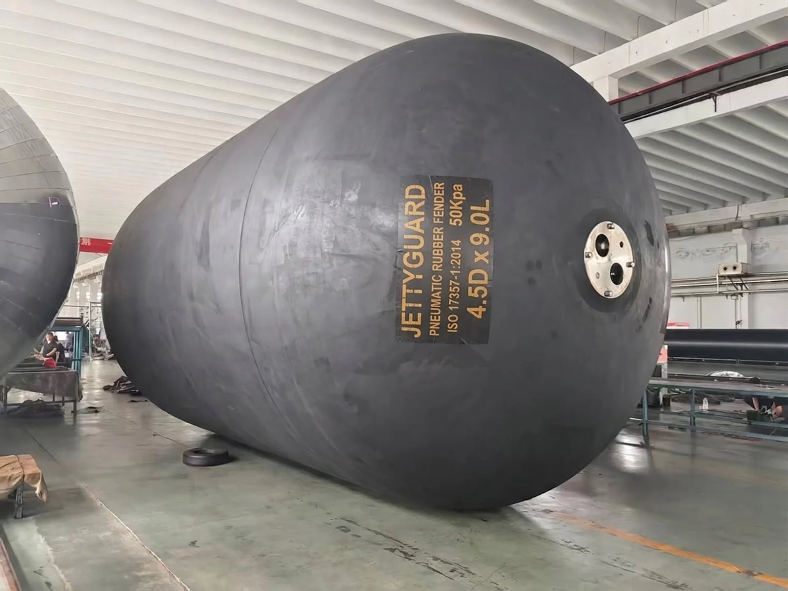
STS Pneumatic Fenders
Ship-to-Ship Transfer Fenders — Vessel-Pair Sized, ISO 17357-1:2014 Certified
Sized to your vessel pair, not pulled from a catalog.
ISO 17357-1:2014 prototype-tested with Clause 12 third-party inspection. OCIMF STS Transfer Guide documentation. Full tire-chain net rigging. One scope.
or browse our full pneumatic fender range
Ship-to-ship transfer fenders are pneumatic rubber fenders deployed between two vessels during STS cargo operations. For Aframax-to-VLCC transfers, the standard selection is a 3300 mm x 6500 mm ISO 17357 Type I (net-type, chain-tire net) fender at 50 kPa IIP. Sizing depends on combined vessel displacement, approach velocity (0.15 m/s sheltered, 0.30 m/s offshore), allowable hull pressure (200 kN/m²), and OCIMF Ship-to-Ship Transfer Guide alignment.
Definition
What Is a Ship-to-Ship Transfer Fender?
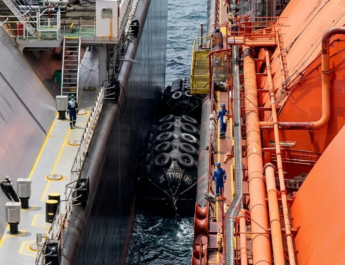
A ship-to-ship transfer fender is a pneumatic rubber fender used to maintain safe separation between two vessels during cargo transfer at sea or at anchorage. Unlike fixed-berth fenders mounted on quay walls, STS fenders must float freely, deploy without fixed infrastructure, and absorb contact energy from two moving hulls simultaneously.
Pneumatic fenders are often called Yokohama fenders, after Yokohama Rubber Co. which originated the floating pneumatic fender design in the 1960s. The terms are interchangeable in current industry usage. ISO 17357-1:2014 is the governing international standard for both product classification and performance testing.
JettyGuard is a marine fender manufacturer producing ISO 17357 pneumatic fenders, including the full tire-chain net rigging scope, for ship-to-ship transfer operations.
Engineering Context
Why STS Fender Specification Differs from Fixed-Berth Fendering
Fixed-berth marine fendering involves a vessel approaching a rigid structure. In FSRU-to-LNGC transfer interfaces and all STS operations, the situation is fundamentally different: both hulls are floating, both are in motion, and the effective berthing energy must account for relative displacement and velocity between two vessels.
Three factors make STS fender sizing more demanding than fixed-berth work:
1. Combined Displacement
The effective berthing energy calculation uses the combined displacement of both vessels. An Aframax (120,000 DWT) alongside a VLCC (320,000 DWT) produces a different energy envelope than either vessel approaching a fixed jetty.
2. Approach Velocity in Open Water
Sheltered anchorage STS operations typically use 0.15 m/s approach velocity. Offshore lightering uses up to 0.30 m/s. These values enter the effective berthing energy equation through PIANC MarCom WG 211 or the OCIMF Ship-to-Ship Transfer Guide (Appendix H) methodology, applying coefficients Cm, Ce, Cs, Cc per PIANC methodology.
3. Allowable Hull Pressure
The reaction force from the fender must stay within the hull plating limits of the smaller vessel, typically 200 kN/m² for double-hull tanker bottom plating. This constraint often governs fender diameter selection ahead of energy absorption capacity.
Specification Data
Pneumatic Fender Sizes for Common STS Vessel Pairings (ISO 17357)
STS fender selection starts with the vessel pair, not a single vessel DWT. All values are nominal at 50 kPa IIP and 60% rated deflection per ISO 17357-1:2014 performance data. Final sizing requires a project-specific berthing energy calculation.
| Vessel Pair | Combined DWT | Fender Size (D x L) | ISO 17357 Type | Energy Absorption (kJ) | Reaction Force (kN) | IIP (kPa) |
|---|---|---|---|---|---|---|
| VLCC x VLCC | 560,000–640,000 | 4.5 x 9.0 m | Type I (CTN) | 4,752 | 5,747 | 50 |
| VLCC x Suezmax | 440,000–480,000 | 3.3 x 6.5 or 4.5 x 9.0 m | Type I (CTN) | 1,814–4,752 | 3,015–5,747 | 50 |
| Suezmax x Aframax | 270,000–300,000 | 3.3 x 6.5 m | Type I (CTN) | 1,814 | 3,015 | 50 |
| Aframax x Panamax | 170,000–200,000 | 2.5 x 5.5 or 3.0 x 5.0 m | Type I (CTN) | 932–1,050 | 2,010–2,030 | 50 |
| LNGC x FSRU | 180,000–260,000 | 3.3 x 6.5 or 4.5 x 9.0 m | Type I (CTN) | 1,814–4,752 | 3,015–5,747 | 50 |
| Product Tanker x Product Tanker | 80,000–120,000 | 2.0 x 3.5 or 2.5 x 4.0 m | Type I or II | 308–663 | 875–1,380 | 50 |
Sizing requires project-specific berthing energy calculation per the OCIMF Ship-to-Ship Transfer Guide (Appendix H) / PIANC MarCom WG 211 (2024) / SIGTTO STS Guidelines. Values above are nominal at 50 kPa IIP and 60% rated deflection. Fenders with 80 kPa IIP are available for higher energy absorption requirements. Contact JettyGuard for project-specific recommendations. See the full pneumatic fender size range for complete data.
Project Sizing
Need a Fender Size Confirmed for Your Vessel Pair?
Share the vessel pair, transfer scenario, and delivery port. We confirm sizing, rigging scope, and documentation before pricing.
Applications
Pneumatic Fender Configurations for STS and Offshore Transfer
Each STS scenario involves different vessel combinations, operating conditions, and rigging requirements. Select the configuration closest to your project.
Crude & Product STS
Aframax–VLCC Tanker Transfers
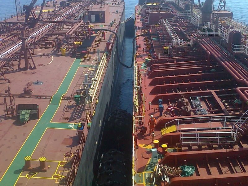
Crude oil and clean product STS transfers between Aframax, Suezmax, and VLCC-class tankers represent the highest-volume STS fender application globally. Fenders are deployed alongside both vessels, typically 4 to 6 units per interface, with tire-chain net (Type I net-type) protection as the standard configuration.
For Aframax-to-VLCC transfers, 3300 mm x 6500 mm fenders at 50 kPa IIP cover most operating scenarios. Where freeboard differential is large or open-water conditions apply, 4500 mm x 9000 mm may be required. JettyGuard supplies the fender body, tire-chain net, chains, shackles, and swivels as one package. One PO, one documentation set, one CIF figure.
Request specification for crude/product STS transfer →LNG STS Transfer
LNGC–FSRU Interfaces
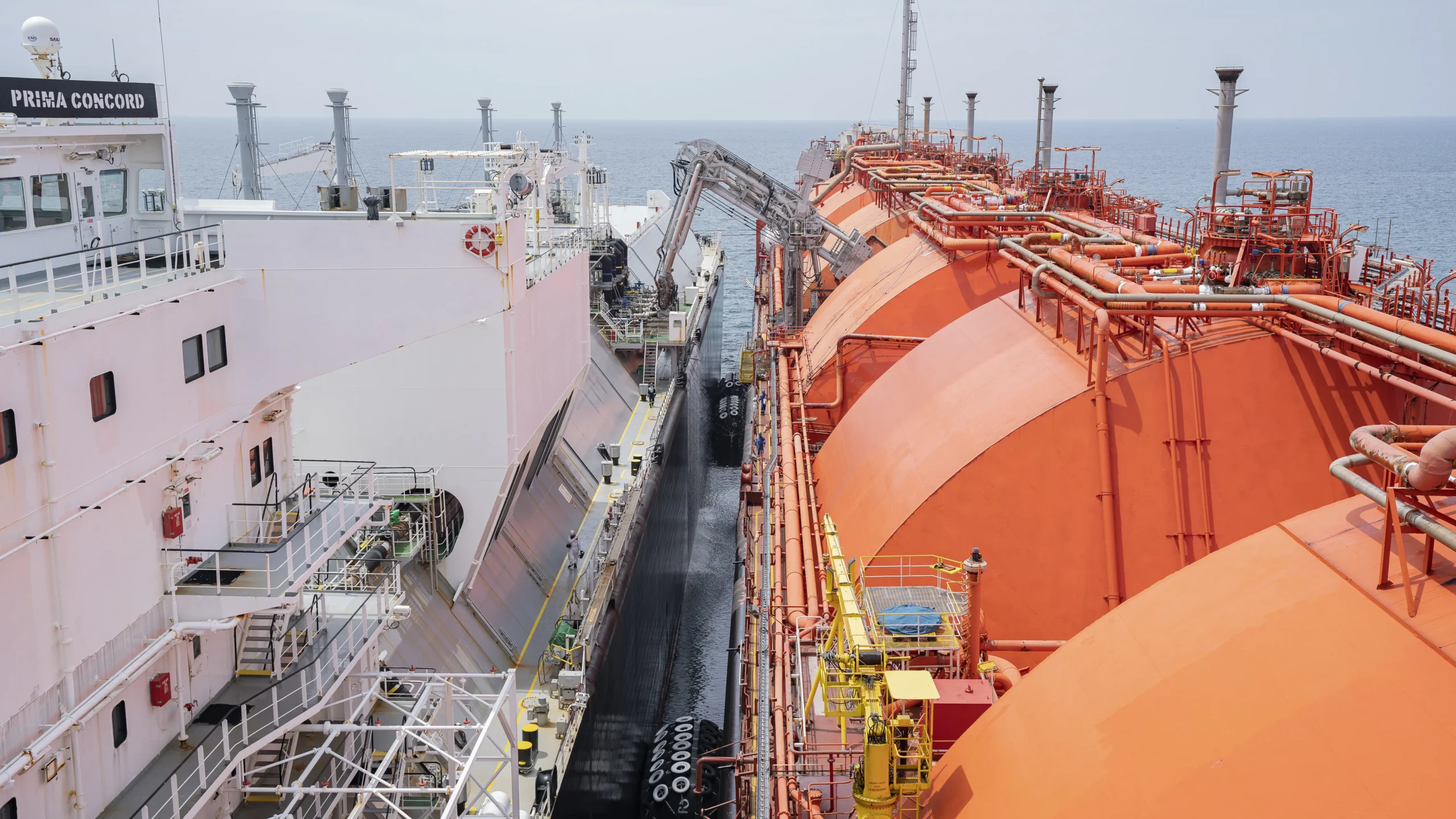
LNG ship-to-ship transfer and LNGC-to-FSRU interfaces operate under tighter performance tolerances than crude STS. The fender must maintain consistent energy absorption across repeated compression cycles, and dimensional consistency between units matters.
Mold-process construction delivers the batch-to-batch consistency that LNG and FSRU project teams require. For LNGC-to-FSRU transfers, 3300 mm x 6500 mm and 4500 mm x 9000 mm are the common specification points, with Clause 8 prototype testing and Clause 12 third-party inspection documenting each fender's actual performance at rated IIP.
For dedicated LNG terminal and FSRU berthing fender requirements, see FSRU and LNG terminal fender systems.
Request specification for LNG STS transfer →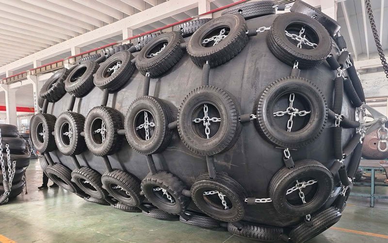
Offshore Lightering
FPSO-to-Shuttle Tanker Offloading
Offshore lightering introduces conditions that sheltered anchorage STS does not face: multi-axis vessel motion, wave-induced contact loads, higher approach velocities (up to 0.30 m/s), and extended deployment periods in open water. FPSO-to-shuttle tanker offloading carries similar demands.
At 0.30 m/s approach velocity, a 3300 mm x 6500 mm fender at 50 kPa IIP absorbs 1,814 kJ at 60% deflection, within the range required for Aframax-to-VLCC lightering. Tire-chain net protection extends service life by distributing contact loads and protecting the rubber body from abrasion. Rigging gear (chains, shackles, swivels, suspension hardware) is supplied as part of the same scope.
Request specification for offshore lightering →SBM & Floating Terminal
Single Buoy Mooring STS Configurations
Single buoy mooring (SBM) systems and floating terminal configurations involve non-standard vessel combinations, variable tidal ranges, and interface conditions that change with sea state and cargo loading. Pneumatic fenders are specified for these applications because reaction force characteristics remain stable across a wide compression range.
For SBM and floating terminal projects still in the specification phase, JettyGuard provides preliminary sizing recommendations based on vessel class, interface geometry, and operating environment, narrowing the specification scope before the project enters formal tendering.
Request specification for SBM / floating terminal →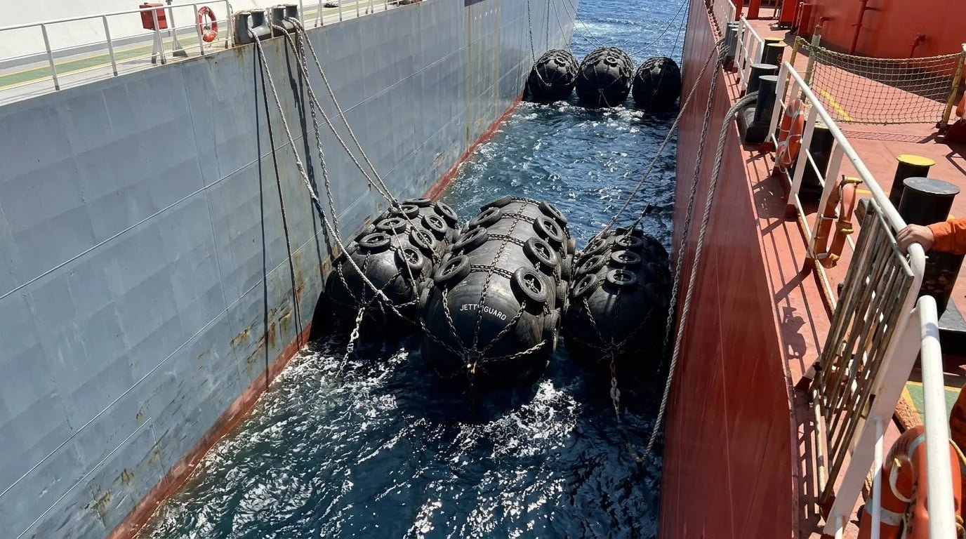
Specification Process
How to Specify a Pneumatic Fender for STS in Five Steps
The selection process below aligns with PIANC MarCom WG 211 (2024) and the OCIMF Ship-to-Ship Transfer Guide methodology.
Identify the Vessel Pair and Displacement
STS fender sizing starts with both vessels. Record the displacement (DWT or full load) of the larger vessel and the smaller vessel. The smaller vessel's hull plating limit typically governs the maximum allowable reaction force.
Calculate Effective Berthing Energy
Apply the berthing energy equation per PIANC MarCom WG 211 or the OCIMF Ship-to-Ship Transfer Guide (Appendix H). Input parameters include approach velocity (0.15 m/s for sheltered anchorage, up to 0.30 m/s for offshore lightering), added mass coefficient (Cm), eccentricity factor (Ce), softness coefficient (Cs), and berth configuration coefficient (Cc). For a detailed walkthrough, see berthing energy calculation methodology.
Check Allowable Hull Pressure
The reaction force from the fender at rated deflection must not exceed the hull plating limit of the smaller vessel, typically 200 kN/m² for double-hull tanker bottom plating. This constraint often determines fender diameter before energy absorption does.
Select ISO 17357 Fender Size
Match the calculated berthing energy and hull pressure limit against ISO 17357-1:2014 performance tables. Select fender diameter, length, IIP (50 or 80 kPa), and ISO 17357 construction type (Type I net-type with chain-tire net, or Type II sling-type).
Confirm Rigging Scope and Documentation
Define tire-chain net configuration, chain working load, shackle rating, and documentation requirements: ISO 17357-1:2014 prototype test certificate per Clause 8, OCIMF Ship-to-Ship Transfer Guide (Appendix H) compliance statement, material test certificates, dimensional inspection records, and third-party inspection requirements (BV / DNV GL / ABS / Lloyd's Register) per Clause 12.

Comparison
Pneumatic vs Foam Fenders for Ship-to-Ship Transfer
STS operations specify pneumatic fenders, not foam-filled, for three operational reasons:
| Criterion | Pneumatic Fender (ISO 17357) | Foam-Filled Fender |
|---|---|---|
| Repeated compression cycle suitability | Designed for thousands of compression cycles in STS service. Air charge restores shape after each contact. | Foam core experiences progressive deflection loss under repeated high-energy compression. Designed for fixed-berth applications with lower cycle frequency. |
| Energy absorption per unit weight | High. Compressed air provides energy absorption at lower fender mass, critical for crane handling and vessel-side deployment. | Lower per unit weight. Solid foam core adds mass without proportional energy gain for STS-scale loads. |
| OCIMF STS Guide alignment for STS | Pneumatic fenders are the referenced fender type in the OCIMF Ship-to-Ship Transfer Guide (Appendix H). | Foam fenders are not referenced in OCIMF STS guidance. Used for fixed-berth and permanent mooring applications. |
Verdict: Pneumatic fenders are the standard for STS transfer. Foam-filled fenders serve a different purpose: permanent quay-wall berthing, donut fenders for SBM/mooring buoys, and fixed installations where the fender is not recovered between operations. For a detailed performance comparison across all application types, see full pneumatic vs foam fender comparison.
STS Fender Supply
Fender Body + Tire-Chain Net + Rigging. One Scope, One PO.
Tell us the vessel pair and we handle the rest.
Standards & Compliance
Standards Governing STS Fenders
STS fender specification is governed by five standards. JettyGuard supplies documentation aligned to all five as standard scope, not as a paid upgrade.
OCIMF Ship-to-Ship Transfer Guide
Appendix H sets out the fender selection calculation and performance criteria for STS transfer, and covers fender deployment, recovery, and inspection protocols. For TMSA or SIRE vetting, this documentation is non-negotiable.
STS Transfer Guide for Petroleum, Chemicals and Liquefied Gases (2013)
Covers the full STS operational workflow: pre-transfer planning, fender positioning, vessel approach, cargo transfer, and fender recovery. References ISO 17357 as the product standard.
ISO 17357-1:2014 — Pneumatic Rubber Fenders
Product manufacturing and testing standard. Defines Type I (net-type, with chain-tire net protection) and Type II (sling-type, no net). Clause 8 requires full-scale prototype performance testing. Every STS fender ships with a Clause 8 prototype test certificate and Clause 9 commercial test report.
STS Transfer Guidelines for LNG
Governs LNG-specific STS operations, including LNGC-to-FSRU transfers. Defines fender performance requirements for cryogenic cargo transfer environments. JettyGuard includes SIGTTO compliance references in the documentation pack for LNG STS projects.
PIANC MarCom WG 211 (2024) — Fender System Design
Provides the engineering methodology for fender system design: berthing energy calculation, fender selection criteria, and hull pressure verification. The effective berthing energy equation and its coefficient definitions originate from PIANC methodology.
Project Delivery
STS Fender Project Delivery: Specification to Anchorage
Every STS fender order follows a five-step workflow. Lead time is committed at PO stage, not "ex works when ready."
Specification Confirmation
Vessel pair, fender size, IIP, ISO 17357 Type, rigging configuration, and documentation confirmed.
Production
Mold-process manufacturing. Rigging gear matched to fender size. Standard: 4–8 weeks. With Clause 12 third-party inspection: 8–14 weeks.
Factory Acceptance Test
Each fender tested at rated IIP per ISO 17357-1:2014 Clause 8 and Clause 9. Third-party inspection (BV / DNV GL / ABS / Lloyd's Register) per Clause 12, coordinated by JettyGuard.
Documentation Pack
ISO 17357-1:2014 Clause 8 prototype test certificate, OCIMF STS Transfer Guide compliance statement, MTC, inspection records, FAT report. Standard scope.
CIF Delivery
Shipped CIF to designated port or anchorage. Scheduling aligned to mobilization window committed at PO. Manufactured by Jettyguard Engineering Technology (Chongqing) Co., Ltd.

FAQ
Frequently Asked Questions — STS Pneumatic Fenders
What size pneumatic fender is needed for STS between an Aframax and a VLCC?
For Aframax-to-VLCC STS transfers, 3300 mm x 6500 mm pneumatic fenders at 50 kPa IIP are the standard specification. Where freeboard differential is large, open-water conditions apply, or the berthing energy calculation per the OCIMF Ship-to-Ship Transfer Guide (Appendix H) produces a higher energy requirement, 4500 mm x 9000 mm may be required. Final sizing depends on combined displacement, approach velocity, and allowable hull pressure on the Aframax hull. Share your vessel pair and we will confirm the recommendation. See the pneumatic fender size chart for the full reference.
What does the OCIMF Ship-to-Ship Transfer Guide require for STS transfer fenders?
The OCIMF Ship-to-Ship Transfer Guide, Appendix H, sets out the fender selection calculation and minimum performance criteria for ship-to-ship transfer operations. Requirements include minimum energy absorption at rated deflection, maximum allowable reaction force relative to hull pressure limits, and a documentation package covering test certificates, inspection records, and material certifications. The Guide also covers the operational STS context: fender deployment, recovery, and inspection protocols. JettyGuard provides the corresponding compliance documentation as standard scope on every STS fender order.
Can foam-filled fenders be used for ship-to-ship transfer?
Pneumatic fenders are the standard for STS operations, referenced in the OCIMF Ship-to-Ship Transfer Guide (Appendix H). They handle repeated compression cycles without permanent deformation, offer higher energy absorption per unit weight for crane deployment, and are the referenced fender type across all major STS operational standards. Foam-filled fenders are designed for permanent quay-wall installations, donut fenders for SBM/mooring buoys, and fixed berths where the fender is not recovered between operations.
How many pneumatic fenders are needed for a standard STS operation?
Most tanker STS operations deploy 4 to 6 pneumatic fenders per vessel interface. The exact count depends on vessel length, freeboard differential, contact area distribution, and the operating environment. OCIMF STS Transfer Guidelines provide minimum coverage recommendations based on vessel class. For VLCC-to-VLCC operations, 6 fenders is common. For Aframax-to-Suezmax, 4 fenders typically provides adequate contact coverage. JettyGuard specifies fender count as part of the sizing recommendation.
Are tire nets and chain rigging required, or optional, for STS fenders?
Tire-chain net protection is required, not optional, for STS fender deployment. The tire net distributes contact loads across the fender surface, protects the rubber body from abrasion and point loading during vessel-to-vessel contact, and extends service life in demanding offshore conditions. Chain rigging (chains, shackles, swivels) connects the fender to the vessel hull and must be rated to the fender mooring load. JettyGuard supplies fender + tire-chain net + rigging as one package under a single PO.
What is the lifespan of a pneumatic fender in continuous STS service?
A well-maintained pneumatic fender in STS service typically operates for 8–12 years. Lifespan depends on operating frequency, compression cycles per deployment, environmental exposure (UV, saltwater), and handling practices during deployment and recovery. Regular inflation pressure checks, visual inspection of the rubber body and tire-net condition, and proper storage between operations extend service life. ISO 17357-1:2014 Clause 8 prototype test certificates document baseline performance at delivery. Periodic re-testing verifies continued compliance.
How does ISO 17357 classify pneumatic fenders for STS use?
ISO 17357-1:2014 defines Type I (net-type, with chain-tire net protection — the standard for STS operations) and Type II (sling-type, no net). Clause 8 requires a full-scale prototype performance test at rated IIP with energy absorption, reaction force, and dimensional measurements documented. Clause 9 requires commercial batch testing on every production order. STS service providers and OCIMF-compliant operators specify Clause 12 third-party inspection for independent verification.
What is the typical lead time for STS fender supply to Asia-Pacific anchorages?
Standard production lead time is 4–8 weeks from PO. ISO 17357-1:2014 with Clause 12 third-party inspection (BV / DNV GL / ABS) requires 8–14 weeks. Third-party inspection is scheduled into the production plan at order confirmation, not added later. CIF delivery to Asia-Pacific anchorages (Singapore, Brisbane, Indonesia, Malaysia) adds 2–4 weeks for sea freight, depending on port. Total PO-to-anchorage: 6–18 weeks. Lead time is committed at PO. The mobilization window is part of the production schedule.
How does JettyGuard compare to Yokohama or Trelleborg for STS fenders?
Same mold-process production method. Same multi-ply cord construction. Same ISO 17357-1:2014 prototype testing and Clause 12 third-party inspection. The price difference reflects manufacturing location and supply chain length, not production method or material specification. The right quality question is not which brand is on the fender. It is which production method was used and whether the certificate documents individual testing. JettyGuard produces every STS fender via mold-process vulcanization with prototype testing at rated IIP, the same method Yokohama and Trelleborg use.
Get Started
Request STS Fender Specifications for Your Project
Tell us the vessel pair, transfer scenario, and delivery port. Your inquiry goes to the founder, not a routing queue, not a sales rep. You'll get a response with fender sizing, rigging scope, and documentation coverage confirmed before we talk pricing.
What to include in your inquiry
Vessel pair (e.g., Aframax + VLCC), transfer type, delivery port, schedule requirements, and any certification or third-party inspection needs. The more context you share, the more specific our recommendation.
You can also browse the full pneumatic fender range to review sizes, types, and performance data.
Fields marked * are required. We respond within one business day.
STS Fender Supply
Need STS Fender Sizing?
Share the vessel pair. We confirm sizing, rigging, and documentation.
Request Specification