

Sizes, Performance Data, Project Drawings
Yokohama Pneumatic Rubber Fenders — ISO 17357, Mould Type and Wrapped Type
JettyGuard's Yokohama-type pneumatic rubber fenders cover 500 × 1000 mm to 4500 × 12000 mm in mould or wrapped type, rigged with tire-chain net, chains, shackles and swivels. Compare the performance data below, then send vessel or berth details for drawings and a quotation.
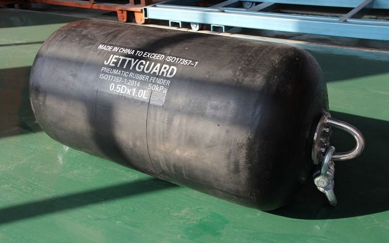
A Yokohama-type pneumatic fender is an inflatable marine fender made from reinforced rubber layers and synthetic cord, designed to absorb berthing energy between vessels or between a vessel and a dock. Compliant with ISO 17357, these fenders are the standard choice for ship-to-ship (STS) transfer operations, FSRU mooring, and offshore terminal berthing. Available in mould type and wrapped type. ISO 17357-1:2014 certified, sizes range from 500×1000 mm to 4500×12000 mm.
Definition
What Is a Yokohama-Type Pneumatic Fender?
The industry-standard floating fender for STS transfer, FSRU mooring, and offshore terminal berthing.
A Yokohama-type pneumatic fender is a floating, inflatable rubber fender used to protect vessel hulls and dock structures during berthing and mooring operations. The name comes from Yokohama Rubber Co., which developed the original design in the 1960s.
Buyers and charterers across marine procurement routinely say “Yokohama fender” when they mean a netted pneumatic rubber fender of this type, so we use the same shorthand on this page. JettyGuard operates as an independent supplier and has no affiliation with Yokohama Rubber Co., Ltd.; the fenders we quote are Yokohama-type units supplied to your project specification. Construction options and selection criteria sit in our pneumatic fender range.
The fender body consists of multiple layers of reinforced rubber and high-tensile synthetic cord, vulcanized into a sealed cylindrical form. Internal air pressure — typically 50 kPa (P50) or 80 kPa (P80) — provides the energy absorption capacity. When compressed between two hulls, the fender deflects and absorbs kinetic energy while the reaction force stays within safe hull pressure limits.
Multi-Layer Rubber, Synthetic Cord, Compressed Air
The fender body is vulcanized from multiple layers of reinforced rubber and high-tensile synthetic cord. Internal air pressure — 50 kPa or 80 kPa — provides the energy absorption capacity.
When compressed between two hulls, the fender deflects and absorbs kinetic energy while reaction force stays within safe hull pressure limits. Two manufacturing methods exist: mould type and wrapped type.
See specifications below ↓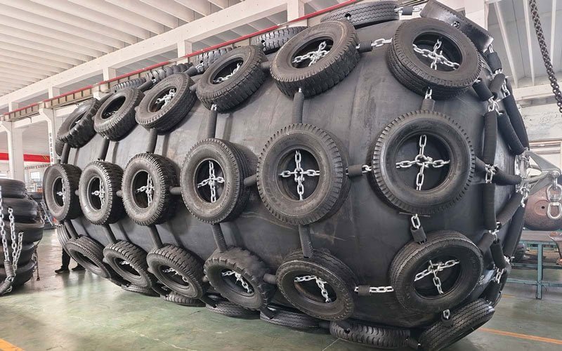
Performance Data
Yokohama Fender Specifications
Performance data at 60% rated deflection per ISO 17357-1:2014. RF = Reaction Force (kN). EA = Energy Absorption (kNm). Tolerance ±10%.
| Size (D×L, mm) | RF @ P50 (kN) | EA @ P50 (kNm) | RF @ P80 (kN) | EA @ P80 (kNm) |
|---|---|---|---|---|
| 500×1000 | 64 | 6 | 80 | 8 |
| 600×1200 | 86 | 10 | 108 | 13 |
| 700×1500 | 137 | 17 | 171 | 21 |
| 1000×1500 | 181 | 32 | 266 | 40 |
| 1350×2500 | 426 | 100 | 533 | 125 |
| 1500×3000 | 579 | 153 | 724 | 191 |
| 1700×3000 | 637 | 190 | 796 | 238 |
| 2000×3500 | 875 | 308 | 1,094 | 385 |
| 2500×4000 | 1,380 | 663 | 1,725 | 829 |
| 2500×5500 | 2,010 | 932 | 2,513 | 1,658 |
| 3000×5000 | 2,030 | 1,050 | 2,538 | 1,313 |
| 3300×6500 | 3,015 | 1,814 | 3,961 | 2,534 |
| 3500×6000 | 3,286 | 2,018 | 4,018 | 2,523 |
| 4500×9000 | 5,747 | 4,752 | 7,551 | 6,633 |
500×1000 mm to 4500×12000 mm
14 standard sizes plus 11 non-standard sizes cover every vessel class — from harbour craft to VLCC lightering. All available at 50 kPa or 80 kPa initial pressure.
Non-standard sizes manufactured on request. Performance tolerance ±10%. Contact us for the full size range or P80 data on additional sizes.
Full tables for every size and rated pressure class sit in our pneumatic fender size chart and performance guide.
Request a custom size quote →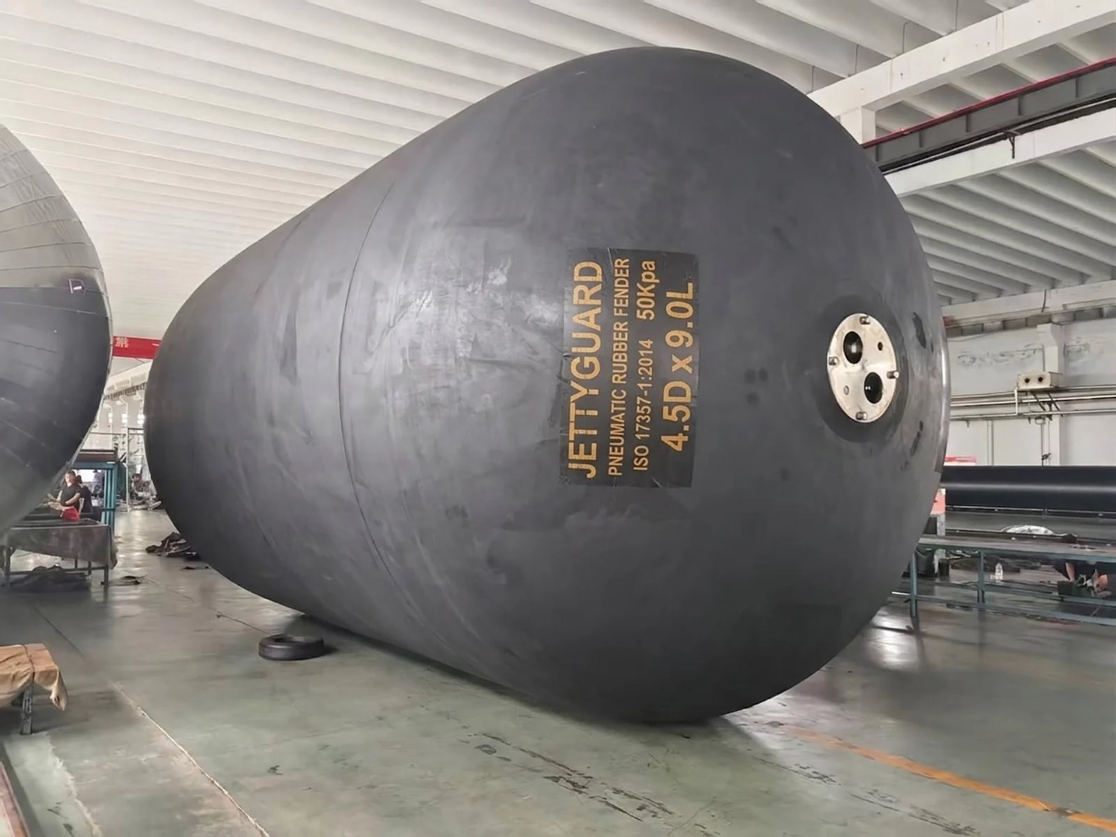
Size Selection
Not sure which size fits your project?
Share your vessel class, application, and delivery port. We will confirm the right size and type before discussing pricing.
Construction Types
Mould Type vs. Wrapped Type: Which Construction Is Right for Your Project?
We manufacture both mould-type and wrapped-type pneumatic fenders, and both meet ISO 17357-1:2014. The right choice depends on your application demands, vessel class, and procurement budget.
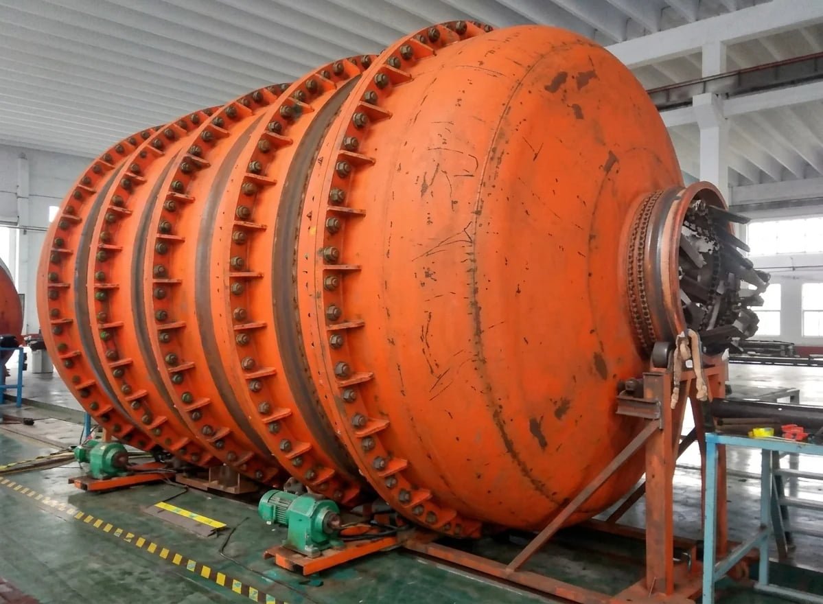
Built Inside a Rigid Steel Mould
Each layer of rubberised tire cord is applied against the mould surface, then hand-stitched to remove trapped air. The rigid backing allows real pressure during stitching — producing high layer-to-layer bond strength.
At the flange ends, tire cord layers pass through a bead ring and turn up inside the mould. This distributes compression and shear loads evenly rather than concentrating stress at the attachment point.
The mould controls outer dimensions precisely. Smooth, uniform surface. Consistent wall thickness (5 mm outer rubber). Cord orientation optimised at 45°–60° means fewer plies for a given burst strength — lower body weight at equivalent performance.
Best fit: STS transfer, LNG/FSRU, OCIMF-compliant projects, high-frequency berthing, 10–15 year service life requirement.
Built Over a Mandrel
Tire cord layers are applied in multiple angles around a mandrel, then the assembly is wrapped in nylon cloth and vulcanised. No mould scheduling required — shorter lead times and reduced tooling cost.
Lower manufacturing cost passes through to procurement pricing. For projects where budget is the primary constraint or compression cycles are infrequent, wrapped-type offers a practical, ISO 17357-1:2014-qualified option.
Easier to produce in very large diameters and extra-long configurations where mould fabrication would be cost-prohibitive. Widely used for ship hull protection and harbour berthing.
Best fit: Ship protection, harbour berthing, cost-sensitive projects, temporary deployment, oversized configurations.
| Criterion | Mould Type | Wrapped Type |
|---|---|---|
| Manufacturing method | Built inside rigid steel mould | Built over a mandrel |
| Layer bonding | Hand-stitched against mould surface — high bond strength | Bonded over a mandrel — adequate when properly executed |
| Flange construction | Bead ring + cord turn-up — even stress distribution | Flange wrapped by cord layers — simpler construction |
| Surface / dimensions | Smooth, uniform, consistent wall thickness | Shape controlled by nylon wrap — verify dimensions on delivery |
| Best applications | STS, LNG/FSRU, OCIMF projects, high-cycle berthing | Ship protection, harbour berthing, cost-sensitive, oversized |
| Relative price | Higher | Lower |
| ISO standard | ISO 17357-1:2014 | ISO 17357-1:2014 |
Not Sure? We’ll Confirm the Right Specification
For STS operations with repeated compression cycles, mould-type construction offers superior layer bonding and dimensional consistency across a multi-fender set.
For ship protection and harbour berthing at lower frequency, wrapped-type delivers the same performance envelope at a lower price point. Share your application and vessel class — we confirm the construction type during review.
Request specification review →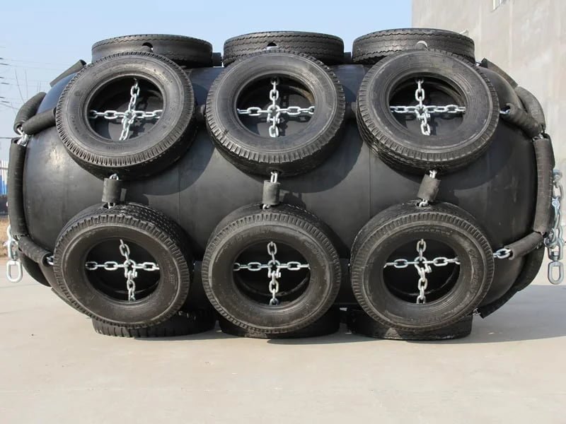
Applications
Applications: Where Yokohama Fenders Are Used
Yokohama-type pneumatic fenders are deployed across four main application categories. Each has different size requirements, rigging configurations, and documentation standards.
STS Operations
Ship-to-Ship (STS) LNG Transfer
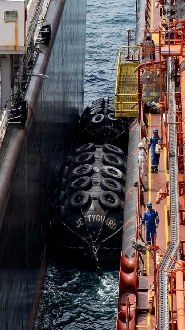
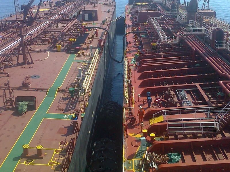
LNG ship-to-ship transfer between an LNG carrier (LNGC) and an FSRU is one of the most demanding fender applications. The fender must maintain consistent energy absorption across repeated compression cycles, and dimensional consistency between units matters when multiple fenders are deployed simultaneously.
Standard specification: 3300×6500 mm and 4500×9000 mm mould-type fenders at 50 kPa IIP. ISO 17357-1:2014 Clause 12 third-party inspection required. For full STS project scope, see our STS transfer fenders page.
Request specification for LNG STS transfer →FSRU & LNG Terminal
FSRU and LNG Terminal Mooring
FSRU mooring operations require fenders that perform reliably across extended deployment periods and variable sea states. The fender must absorb berthing energy from a large LNG carrier approaching the FSRU hull, then remain in position during the full transfer window.
Mould-type fenders at 50 kPa IIP are the standard for FSRU applications. Size selection depends on LNGC displacement and approach velocity. See our FSRU fender systems page for dedicated requirements.
Request specification for FSRU mooring →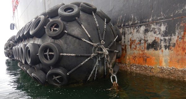
Offshore & SPM
Offshore SPM and CBM Terminals
Single point mooring (SPM) and conventional buoy mooring (CBM) terminals use pneumatic fenders to protect tanker hulls during approach and mooring. Offshore conditions introduce higher approach velocities (up to 0.30 m/s) and multi-axis vessel motion compared to sheltered anchorage STS.
3300×6500 mm and 4500×9000 mm fenders at 50 or 80 kPa IIP cover most offshore scenarios. Tire-chain net (Type I) protection is standard for offshore deployment. See OCIMF requirements applicable to these operations.
Request specification for offshore/SPM →Shipyard & Drydock
Shipyard and Drydock Operations
Shipyards use pneumatic fenders for vessel launching, drydock positioning, and hull protection during fitting-out. These applications typically involve lower berthing energy than STS or offshore work, and fenders are deployed temporarily rather than left in service.
Sling-type (Type II) fenders in sizes from 700×1500 mm to 2000×3500 mm cover most shipyard applications. Wrapped-type construction is a cost-effective choice where Clause 12 third-party inspection is not required.
Request specification for shipyard use →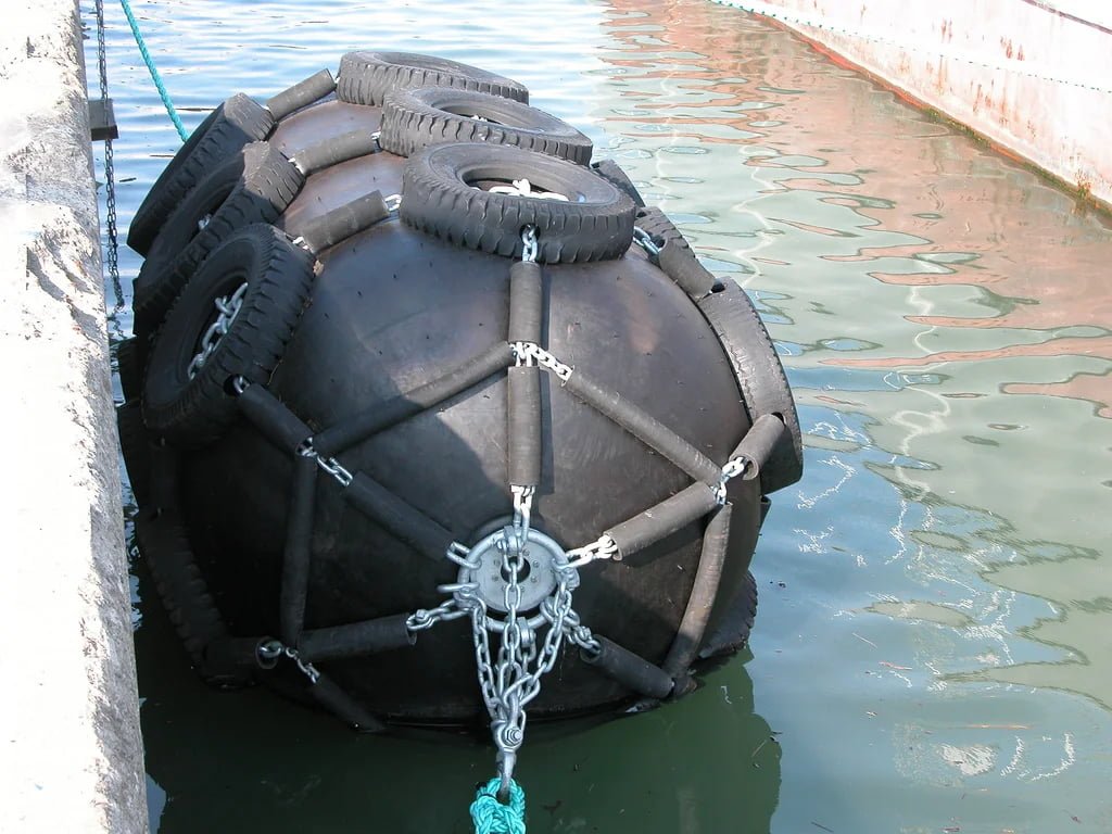
Standards & Compliance
ISO 17357 Compliance and Quality Documentation
JettyGuard Yokohama-type fenders are manufactured and tested in accordance with ISO 17357-1:2014. Documentation is standard scope, not a paid upgrade.
High-Pressure Pneumatic Fender Standard
Covers high-pressure floating pneumatic rubber fenders (50 kPa and 80 kPa initial inflation pressure). Defines Type I (net-type, with chain-tire net protection) and Type II (sling-type, no net). Specifies a three-tier quality framework: Clause 8 (prototype testing), Clause 9 (commercial batch testing), and Clause 12 (third-party independent inspection).
Low-Pressure Pneumatic Fender Standard
Covers low-pressure floating pneumatic rubber fenders (7 kPa initial inflation pressure), made from vulcanized-rubber-coated textile rather than synthetic-tyre-cord reinforced rubber. A fundamentally different product category, covered by Part 2 of the standard.
STS Operations
Ship-to-Ship Transfer Guide, Appendix H. Sets out the fender selection calculation and performance criteria for STS operations. JettyGuard provides the corresponding compliance statements as standard documentation on STSfender orders.
Terminal Design
MarCom WG 211 (2024), Guidelines for the Design of Fender Systems (superseding WG33). Provides the engineering methodology for terminal fender design, including berthing energy calculation and fender selection criteria.
Individual Test Certificates
Every fender ships with an ISO 17357-1:2014 Clause 8 prototype test certificate documenting actual performance at rated IIP. Energy absorption and reaction force measured and documented per unit.
BV / DNV GL / ABS / Lloyd's
Third-party inspection coordinated by JettyGuard and scheduled into the production plan at order confirmation. BV, DNV GL, ABS, or Lloyd's Register available. Not an add-on — scheduled at PO.
Every Fender Ships with Individual Test Data
ISO 17357-1:2014 Clause 8 prototype test certificate documents actual energy absorption and reaction force at rated IIP — per unit, not per batch.
Third-party inspection (BV, DNV GL, ABS, Lloyd’s Register) is scheduled into production at order confirmation. Not a paid upgrade — standard scope.
Request documentation details →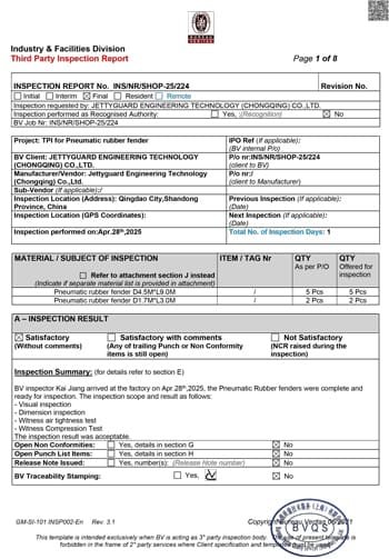
Documentation
Need ISO 17357-1:2014 test certificates and OCIMF STS Guide documentation?
Every JettyGuard order includes full documentation as standard. Tell us your project requirements and we will confirm the documentation scope.
Why JettyGuard
Why Source from JettyGuard
One supplier, one documentation set, one CIF figure for the complete scope.
Full size range
500×1000 mm to 4500×12000 mm as standard. Non-standard sizes available. You do not need a second supplier for large-diameter fenders.
Dual construction
Mould type and wrapped type from the same factory. We recommend the right type for your application, not the one that is easier to produce.
Complete rigging scope
Fender body plus rigging (net, chains, shackles, swivels) under one PO. One documentation set covers the full scope.
ISO 17357-1:2014 tested as standard
Individual testing with measured performance data per fender. Not batch testing unless you specify otherwise.
Lead time committed at PO
Standard production: 4–8 weeks. With Clause 12 third-party inspection: 8–14 weeks. The mobilization window is part of the production schedule.
CIF delivery
Delivered to your project port or anchorage. Not ex-works.
Optional On-Site Installation Supervision
Installation manuals ship with every order. On large or sequence-critical projects, a technician can attend site under a separate, project-specific quotation to guide fender placement and installation. Local labor, lifting equipment, compressor, tools, permits and site resources remain client-coordinated as applicable.
Chargeable CTN Replacement and Overhaul
Quoted separately and outside the product price, this project-specific package can cover supply of a replacement chain-tire net (CTN) assembly, technical supervision of net removal and refitting, safety-valve overhaul, final inspection and pressure testing. Local labor, lifting resources, compressor, tools, permits and site resources remain client-coordinated as applicable.
Manufacturer
Jettyguard Engineering Technology (Chongqing) Co., Ltd.
Every fender we ship carries our name on the certificate.
FAQ
Frequently Asked Questions — Yokohama Pneumatic Fenders
What is a Yokohama-type pneumatic fender?
A Yokohama-type pneumatic fender is an inflatable marine fender made from reinforced rubber and synthetic cord, designed to absorb berthing energy in ship-to-ship transfer and terminal mooring operations. The name comes from Yokohama Rubber Co., which developed the original design in the 1960s. Today it is the standard industry term for floating pneumatic fenders of this construction type. Compliant with ISO 17357-1:2014 (both mould type and wrapped type), sizes range from 500×1000 mm to 4500×12000 mm.
What is the difference between mould-type and wrapped-type Yokohama fenders?
Mould-type fenders are vulcanized in a single mould cycle, producing a seamless rubber body with consistent wall thickness. Wrapped-type fenders are built by wrapping rubber and cord plies around a mandrel before vulcanization. Both meet ISO 17357 performance requirements. Mould type offers higher dimensional precision and is recommended for STS and LNG/FSRU applications. Wrapped type is lower cost and suited to ship protection and harbor berthing where Clause 12 third-party inspection is not required.
What size Yokohama fender do I need for ship-to-ship transfer?
For Aframax-to-VLCC STS transfers, 3300×6500 mm at 50 kPa IIP is the standard specification. For VLCC-to-VLCC or LNGC-to-FSRU operations, 4500×9000 mm is common. Final sizing requires a berthing energy calculation per the OCIMF Ship-to-Ship Transfer Guide (Appendix H) or PIANC MarCom WG 211, using combined vessel displacement, approach velocity, and allowable hull pressure on the smaller vessel. Share your vessel pair and we will confirm the recommendation.
What is the working pressure of a Yokohama fender?
Standard initial internal pressure (IIP) is 50 kPa (P50). An 80 kPa (P80) option is available for higher energy absorption requirements. The safety valve is set at 175 kPa for P50 fenders (sizes 2500 mm and above). Testing pressure is 250 kPa (P50) or 300 kPa (P80). The 50 kPa standard matches the OCIMF design basis directly.
How long do Yokohama pneumatic fenders last?
A well-maintained pneumatic fender in STS service typically operates for 8–12 years. JettyGuard mould-type fenders under our recommended maintenance programme achieve 15+ years of service life. Lifespan depends on operating frequency, compression cycles per deployment, UV and saltwater exposure, and handling practices during deployment and recovery. Regular inflation pressure checks, visual inspection of the rubber body and tire-net condition, and proper storage between operations extend service life. ISO 17357-1:2014 Clause 8 prototype test certificates document baseline performance at delivery.
Are Yokohama fenders compliant with ISO 17357?
Yes. JettyGuard Yokohama-type fenders are manufactured and tested in accordance with ISO 17357-1:2014. Clause 8 requires a full-scale prototype performance test at rated IIP with energy absorption, reaction force, and dimensional measurements documented per unit. Every fender ships with Clause 8 and Clause 9 test documentation. Third-party inspection per Clause 12 by BV, DNV GL, ABS, or Lloyd's Register is available and coordinated by JettyGuard.
What is the difference between a Yokohama fender and a foam-filled fender?
Yokohama pneumatic fenders use compressed air for energy absorption and are designed for repeated compression cycles in STS and offshore service. Foam-filled fenders use a closed-cell EVA foam core and are designed for permanent quay-wall berthing and fixed installations. Pneumatic fenders are the referenced fender type in the OCIMF Ship-to-Ship Transfer Guide (Appendix H). Foam-filled fenders are not referenced in OCIMF STS guidance. For STS transfer and FSRU mooring, pneumatic fenders are the correct choice.
Project Inquiry
Request Yokohama Fender Specifications for Your Project
Tell us the application, vessel class, and delivery port. Your inquiry goes directly to the founder. You will get a response with fender sizing, rigging scope, and documentation coverage confirmed before we discuss pricing.
What to include
- • Application type (STS, FSRU, offshore, shipyard)
- • Vessel class or DWT (both vessels for STS)
- • Fender size if known, or “not sure”
- • Delivery port and required timeline
- • Certification requirements (ISO 17357-1:2014, OCIMF, 3rd party inspection per Clause 12)
You can also browse the full pneumatic fender range to review sizes, types, and performance data.
All fields marked * are required. We respond within 1 business day.
ISO 17357 Certified
Get Yokohama fender specs for your project
Mould type & wrapped type. Full size range. CIF delivery.
Request Fender Specification