
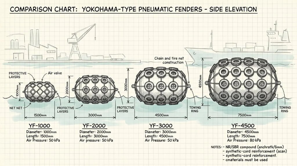
Most fender inquiries start with a size question. The vessel class is known, the berthing energy is estimated, but the right fender size is not immediately obvious from a product catalog.
Standard pneumatic fenders under ISO 17357-1:2014 range from 500×1000 mm to 4500×12000 mm in diameter × length. Performance is rated at 60% deflection and 50 kPa initial inflation pressure. The most common sizes for LNG terminal and STS operations are 2500×5500 mm (943 kJ), 3300×6500 mm (1,814 kJ), and 4500×9000 mm (4,752 kJ). Custom sizes outside the standard range are permitted under Clause 6.3.3.
This chart covers all standard sizes — including what Yokohama-type pneumatic fenders are built to. “Yokohama fender” is a generic industry term for the same product category governed by ISO 17357-1:2014.
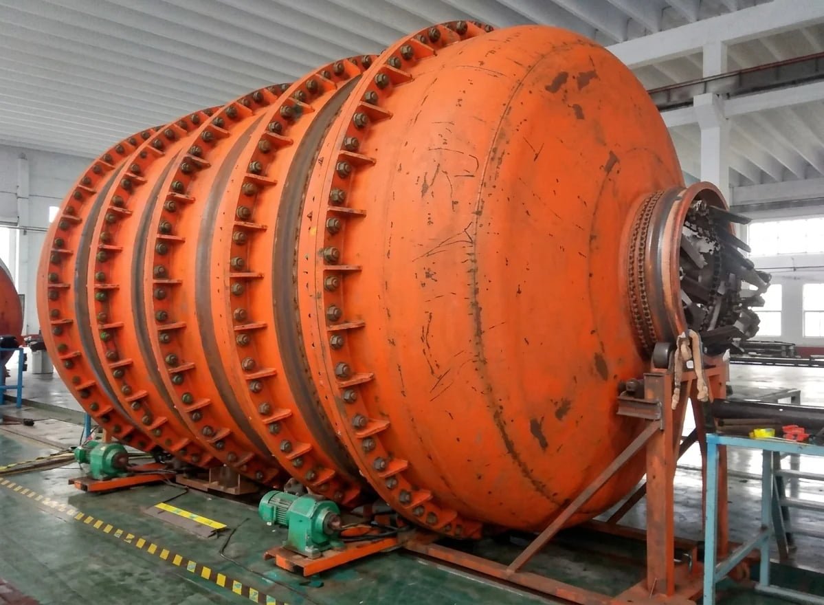
Standard Pneumatic Fender Sizes Under ISO 17357-1:2014
The following table lists all standard pneumatic fender sizes defined in ISO 17357-1:2014, with Guaranteed Energy Absorption (GEA) and Reaction Force (RF) at 60% deflection and 50 kPa initial inflation pressure.
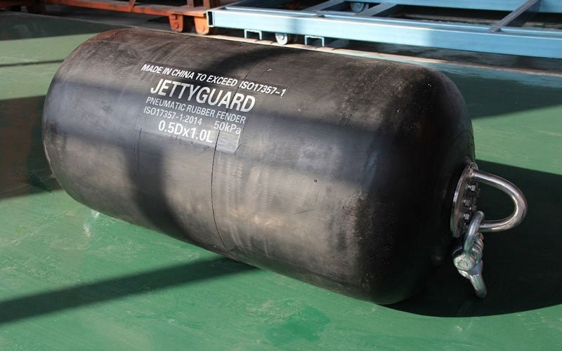
Table 1: Standard Pneumatic Fender Sizes — ISO 17357-1:2014, 60% Deflection, 50 kPa IIP
| Size (D×L mm) | GEA (kJ) | RF (kN) | Hull Pressure (kPa) |
|---|---|---|---|
| 500×1000 | 6 | 64 | 132 |
| 600×1000 | 8 | 74 | 126 |
| 700×1500 | 17 | 137 | 135 |
| 1000×1500 | 32 | 182 | 122 |
| 1000×2000 | 45 | 257 | 132 |
| 1200×2000 | 63 | 297 | 126 |
| 1350×2500 | 102 | 427 | 130 |
| 1500×3000 | 153 | 579 | 132 |
| 1700×3000 | 191 | 639 | 128 |
| 2000×3500 | 308 | 875 | 128 |
| 2500×4000 | 663 | 1,381 | 137 |
| 2500×5500 | 943 | 2,019 | 148 |
| 3300×4500 | 1,175 | 1,884 | 130 |
| 3300×6500 | 1,814 | 3,015 | 146 |
| 3300×10600 | 3,067 | 5,257 | 158 |
| 4500×9000 | 4,752 | 5,747 | 146 |
| 4500×12000 | 6,473 | 7,984 | 154 |
GEA and RF values are at 60% deflection and 50 kPa initial inflation pressure. Values at 80 kPa IIP are approximately 30–40% higher — consult manufacturer data sheets for exact performance curves. Hull pressure is the internal air pressure at GEA deflection, equal to the pressure applied to the vessel hull contact area.
This table is not exhaustive. Manufacturers offer intermediate sizes between these standard designations. For the full ISO 17357-1:2014 standard requirements, including testing procedures and material specifications, see our standard explainer.
How to Read the Size Chart
The size designation “D×L” means outer diameter × overall length in millimetres, measured at the rated initial inflation pressure (IIP). A 3300×6500 fender is 3.3 metres in diameter and 6.5 metres long when inflated to 50 kPa.
Performance is rated at 60% deflection — the point where the fender is compressed to 40% of its original diameter. This is the rated performance point, not the maximum compression limit. Going beyond 60% risks permanent deformation.
Guaranteed Energy Absorption (GEA): The minimum energy a fender must absorb at 60% deflection under ISO 17357-1:2014 Clause 8 prototype testing. Expressed in kilojoules (kJ). The fender must meet or exceed this value — there is no lower tolerance.
Reaction Force (RF): The force the fender exerts on the vessel hull at 60% deflection. Expressed in kilonewtons (kN). ISO 17357-1:2014 allows ±10% tolerance on the rated RF value.
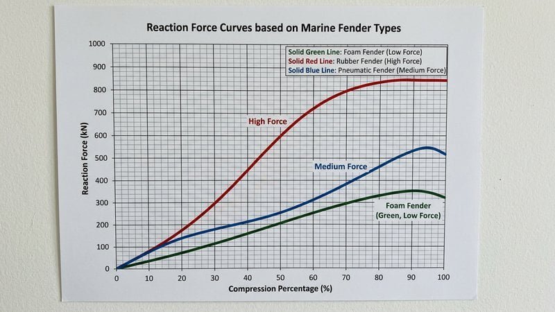
RF matters as much as GEA for size selection. A fender that absorbs enough energy but generates excessive hull pressure can still damage an LNG carrier’s membrane tank containment. Always check that the RF divided by the contact area stays within the vessel’s hull pressure limit.
Two pressure ratings exist: 50 kPa and 80 kPa IIP. Pneumatic 50 is standard for most applications. Pneumatic 80 delivers roughly 30–40% more GEA per unit size — used where installation space is limited or berthing energy is high relative to available berth geometry.
Selecting the Right Size: Key Inputs
Three inputs are needed before matching a size from the chart:
1. Effective Kinetic Energy (EKE) — Vessel displacement × berthing velocity² × correction coefficients (eccentricity, berth configuration, softness, added mass). This is the energy the fender must absorb. Calculated per PIANC MarCom Report No. 211 (2024).
2. Vessel class and hull pressure limit — gas carriers (LNG/LPG) allow up to 200 kN/m² per PIANC WG211 Table 6-6. Larger tankers and bulk carriers tolerate higher values. The fender’s RF divided by contact area at 60% deflection must stay below this limit.
3. Approach velocity and exposure class — PIANC 211 assigns berthing velocities by vessel size and exposure level. A sheltered berth with tug assist might use 0.10 m/s; an exposed offshore SPM uses 0.25–0.30 m/s.
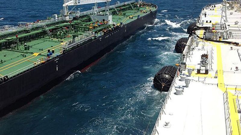
Quick example: An 80,000 DWT tanker at 0.15 m/s approach, with Cm=1.8, Ce=0.5, Cc=1.0, Cs=1.0 yields approximately 350 kJ effective berthing energy. Apply a safety factor of 1.5 → required GEA ≥ 525 kJ. From Table 1, the 2500×5500 mm fender (943 kJ at 50 kPa) provides adequate margin. The 2500×4000 mm (663 kJ) also works but with a shorter contact length.
Do not select a size from the chart alone — always verify hull pressure against the vessel’s structural limits. For the full step-by-step methodology, see our pneumatic fender selection guide for LNG terminals.
Size by Application
The table below maps common application types to typical fender sizes. These are starting points for initial budgeting and space planning — not final specifications.
Table 2: Typical Pneumatic Fender Sizes by Application
| Application | Typical Vessel Class | Recommended Size (D×L mm) | GEA (kJ) | Reference |
|---|---|---|---|---|
| Harbour berthing | Up to 5,000 DWT | 1000×2000 | 45 | Low-energy berthing |
| Port quay berthing | 5,000–30,000 DWT | 1500×3000 to 2000×3500 | 153–308 | Standard port operations |
| Ship-to-ship transfer (STS) | 30,000–80,000 DWT | 2500×5500 to 3300×6500 | 943–1,814 | OCIMF STS Transfer Guide |
| LNG carrier / FSRU berthing | 80,000–180,000 m³ | 3300×6500 to 4500×9000 | 1,814–4,752 | SIGTTO / PIANC 211 |
| SPM / offshore mooring | Tankers, FSOs | 2500×4000 to 3300×4500 | 663–1,175 | High-energy offshore impact |
| Drydock / shipyard | All vessel types | 1000×2000 to 2500×5500 | 45–943 | Temporary deployment |
These are indicative starting points. Final size selection requires a berthing energy calculation per PIANC MarCom 211. See our pneumatic fender selection methodology for the full calculation approach.
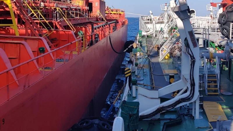
For Yokohama-type pneumatic fenders used in STS and LNG operations, the 3300×6500 mm and 4500×9000 mm sizes account for the majority of project specifications worldwide.
Custom Sizes Outside the Standard Range
ISO 17357-1:2014 Clause 6.3.3 explicitly permits custom sizes outside the 14 standard designations listed in Table 1. The fender must satisfy the same performance requirements — GEA, RF, deflection curve — verified through Clause 8 prototype testing.
Custom sizes are common for:
– FSRU retrofit projects where berth geometry constrains diameter
– SPM terminals with non-standard vessel approach angles
– Applications requiring diameter-to-length ratios outside the standard series
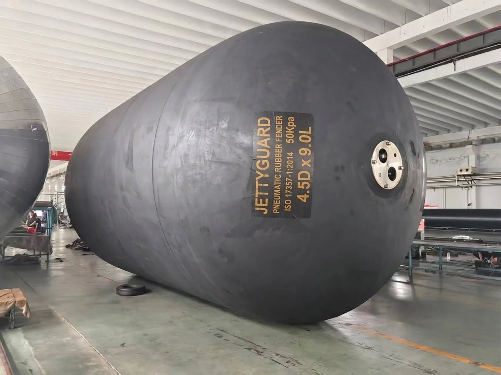
When specifying a custom size, the buyer must define: diameter, length, required GEA, maximum allowable RF, initial inflation pressure (50 or 80 kPa), and construction type (Type I or Type II).
Custom fenders require prototype testing under Clause 8, which adds lead time. Standard sizes typically ship in 4–6 weeks; custom sizes require 8–14 weeks including test scheduling and documentation.
JettyGuard supplies pneumatic fenders in both standard and custom sizes. Send us your vessel dimensions and berthing conditions for a size recommendation.
Frequently Asked Questions
What is the standard size range for pneumatic fenders?
Under ISO 17357-1:2014, standard pneumatic fender sizes range from 500×1000 mm to 4500×12000 mm (diameter × length). The most common sizes for commercial port and offshore applications are 1500×3000 mm through 4500×9000 mm. Sizes outside this range are permitted under Clause 6.3.3 as custom designs subject to the same performance requirements.
What size pneumatic fender is used for ship-to-ship transfer?
For STS operations involving vessels of 30,000–80,000 DWT, the OCIMF STS Transfer Guide references fenders in the 2500×5500 mm to 3300×6500 mm range, providing 943–1,814 kJ GEA at 60% deflection. Larger tankers above 80,000 DWT typically require 3300×6500 mm or 4500×9000 mm fenders. Final size depends on berthing velocity and vessel displacement.
What do GEA and RF mean on a pneumatic fender size chart?
GEA (Guaranteed Energy Absorption) is the minimum energy the fender must absorb at 60% deflection, expressed in kJ. RF (Reaction Force) is the force the fender exerts on the vessel hull at 60% deflection, expressed in kN. Both values are rated at 50 kPa initial inflation pressure under ISO 17357-1:2014 Clause 8 prototype testing.
Can pneumatic fenders be made in custom sizes?
Yes. ISO 17357-1:2014 Clause 6.3.3 permits custom sizes outside the standard series, provided the fender meets the same performance requirements under Clause 8 prototype testing. Custom sizes are common for FSRU projects, SPM terminals, and retrofit applications where standard sizes do not match the vessel geometry.
Need a size recommendation for your project? Send JettyGuard your vessel class and berthing energy requirements — we confirm the correct fender specification during engineering review.