
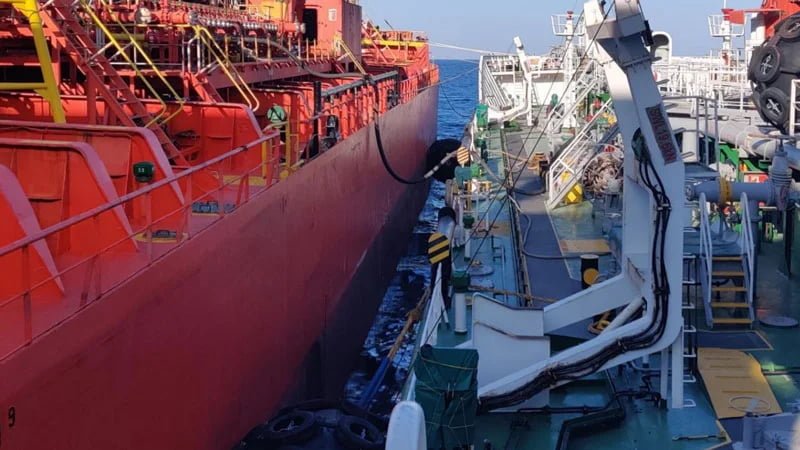
The OCIMF Ship to Ship Transfer Guide is the governing reference for STS fender selection. But the actual requirements — fender sizes, quantities, velocity assumptions, and calculation methods — are scattered across tables and formulas that many procurement teams never see in full. This article lays out those requirements clearly.
The OCIMF STS Transfer Guide specifies pneumatic fenders at 50 kPa initial pressure for all ship-to-ship operations. Fender size ranges from 1.0×2.0 m to 4.5×9.0 m based on equivalent displacement coefficient. Minimum quantity ranges from 3 to 5 fenders depending on the equivalent displacement coefficient — the requirement is non-monotonic, so always read the exact table row rather than assuming quantity rises steadily with vessel size.
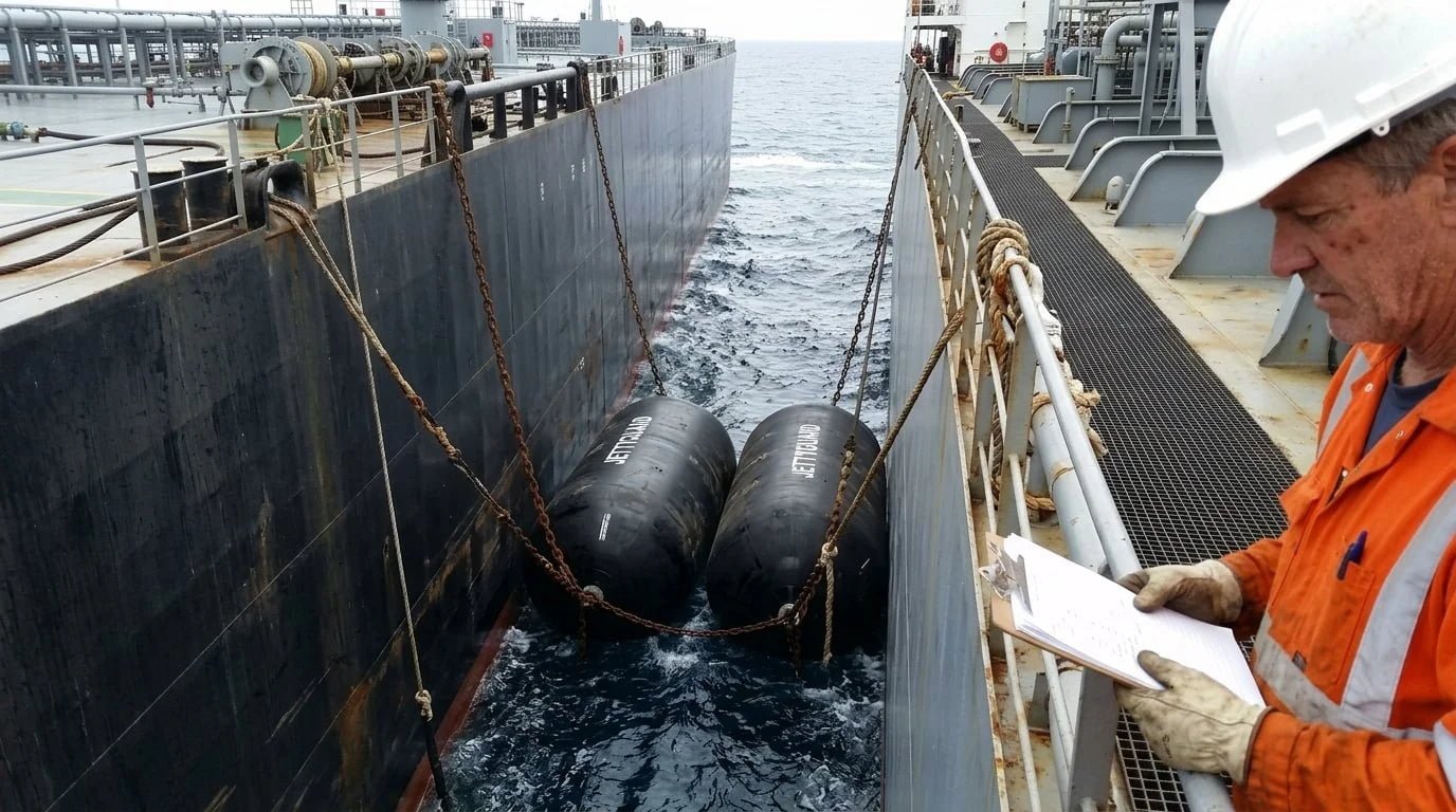
What Is OCIMF and What Does the STS Transfer Guide Cover?
OCIMF — the Oil Companies International Marine Forum — is an industry body representing oil companies with interests in the shipment and terminalling of crude oil, oil products, petrochemicals, and gas. Founded in 1970, its membership includes major operators like Shell, BP, ExxonMobil, and TotalEnergies.
The Ship-to-Ship Transfer Guide for Petroleum, Chemicals and Liquefied Gases is published jointly by CDI, ICS, OCIMF, and SIGTTO. It covers the full scope of STS operations: approach procedures, mooring arrangements, cargo transfer, and — critically for this article — fender system requirements.
The Guide is not optional. Port authorities, terminal operators, and P&I clubs treat it as the minimum standard. If your fender system does not meet these requirements, the operation gets flagged during vetting. Insurance coverage may be affected.
Fender Selection Criteria in the OCIMF Guide
The OCIMF Guide uses a three-step process for OCIMF fender selection:
Step 1 — OCIMF Table Selection. Calculate the equivalent displacement coefficient (C) from the two vessel displacements. Look up the recommended fender size from the OCIMF fender selection table.
Step 2 — Berthing Energy Calculation. Calculate the actual berthing energy (E) using virtual weights, approaching velocity, eccentricity coefficient, and safety factor.
Step 3 — Confirmation. Compare the selected fender’s maximum energy absorption (Ef) against calculated berthing energy (E). If Ef > E, the selection is confirmed. If not, upgrade the fender diameter.
Equivalent Displacement Coefficient
The coefficient C is calculated as:
C = (2 × W_A × W_B) / (W_A + W_B)
Where W_A is the displacement of the larger vessel and W_B is the displacement of the smaller vessel.
Three Operation Types
The Guide defines three STS operation types:
| Operation Type | Ship A (Larger) | Ship B (Smaller) |
|---|---|---|
| Full-Full Berthing | Discharging ship (Full) | Receiving ship (Full) |
| Ordinary Lightering | Discharging ship (Full) | Receiving ship (Ballast) |
| Reverse Lightering | Receiving ship (Ballast) | Discharging ship (Full) |
The Guide specifies that fender systems should be selected for the worst-case Full-Full condition — even for lightering operations. At the severest condition, both vessels approach full displacement regardless of operation type.
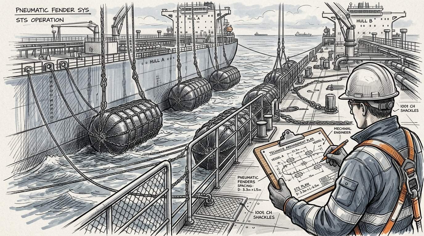
OCIMF Fender Size and Quantity Requirements
The following table reproduces the OCIMF fender size selection table — the quick reference for fender selection in STS operations covering petroleum, chemicals, and liquefied gases:
| Equivalent Displacement Coefficient (C) | Berthing Energy (t·m) | Relative Velocity (m/s) | Fender Size D×L (m) | Min. Quantity |
|---|---|---|---|---|
| 1,000 | 2.4 | 0.30 | 1.0 × 2.0 | 3+ |
| 3,000 | 7.0 | 0.30 | 1.5 × 3.0 | 3+ |
| 6,000 | 14.0 | 0.30 | 2.5 × 5.5 | 3+ |
| 10,000 | 17.0 | 0.25 | 2.5 × 5.5 | 3+ |
| 30,000 | 40.0 | 0.25 | 3.3 × 6.5 | 4+ |
| 50,000 | 48.0 | 0.20 | 3.3 × 6.5 | 4+ |
| 100,000 | 54.0 | 0.15 | 3.3 × 6.5 | 4+ |
| 150,000 | 71.0 | 0.15 | 3.3 × 6.5 | 5+ |
| 200,000 | 93.0 | 0.15 | 3.3 × 6.5 | 5+ |
| 330,000 | 155.0 | 0.15 | 4.5 × 9.0 | 4+ |
| 500,000 | 231.0 | 0.15 | 4.5 × 9.0 | 4+ |
Source: Ship-to-Ship Transfer Guide for Petroleum, Chemicals and Liquefied Gases, CDI/ICS/OCIMF/SIGTTO.
The table assumes Calm weather conditions and 50 kPa initial internal pressure (Pneumatic 50). If the coefficient C falls between two values, select the fender size for the larger coefficient.
A safety factor (SF) between 1.0 and 2.0 should be applied to the berthing energy calculation for abnormal berthing conditions.
Approaching Velocity and Weather Conditions
The OCIMF Guide defines three weather conditions with corresponding approaching velocities:
| DWT Range | Calm (Sea State 0–3, Hs 0–1.25 m) | Moderate (Sea State 4, Hs 1.25–2.5 m) | Rough (Sea State 5, Hs 2.5–4.0 m) |
|---|---|---|---|
| < 10,000 | 0.30 m/s | 0.40 m/s | 0.50 m/s |
| 10,000–50,000 | 0.25 m/s | 0.325 m/s | 0.40 m/s |
| 50,000–100,000 | 0.20 m/s | 0.25 m/s | 0.30 m/s |
| > 100,000 | 0.15 m/s | 0.20 m/s | 0.25 m/s |
The OCIMF selection table is designed for Calm conditions. If your STS operation area experiences Moderate or Rough sea states, the higher approaching velocity increases berthing energy — and the fender must be upgraded.
The recommended upgrade path is to increase fender diameter. Increasing fender length or raising initial internal pressure from 50 kPa to 80 kPa is not recommended. Higher pressure makes the force-deflection curve steeper without meaningfully increasing allowable compression capacity.
What This Means for Your Fender Procurement
Translating OCIMF fender guidelines into procurement decisions:
1. Always select for Full-Full worst case. Even if your operation is lightering only, the severest moment approaches full-full displacement. The Guide is explicit about this.
2. Confirm 50 kPa initial pressure test data. The OCIMF tables assume Pneumatic 50. Ask your supplier for performance data at 50 kPa — not 80 kPa. Performance curves at 80 kPa look better on paper but do not match the OCIMF design basis.
3. Request ISO 17357-1:2014 type test reports. The standard covers material testing, burst pressure, air-tightness, and performance at rated conditions. A certificate alone is not enough — ask for the test report with actual measured values.
4. Upgrade by diameter, not by length or pressure. If the selection table puts you between sizes, go to the next diameter up. A 3.3 m diameter fender has a fundamentally different energy absorption characteristic than a longer 2.5 m fender pressurized to 80 kPa.
5. Confirm minimum quantity from the exact table row. Three fenders is the minimum for smaller vessel combinations, rising to 4 or 5 at higher coefficients — but the requirement is non-monotonic (for example, 150,000 requires 5+, while 330,000 and 500,000 only require 4+). Do not interpolate or assume quantity rises steadily with vessel size; read the specific row for the calculated coefficient. This is a hard requirement, not a suggestion.
How JettyGuard Meets OCIMF Requirements
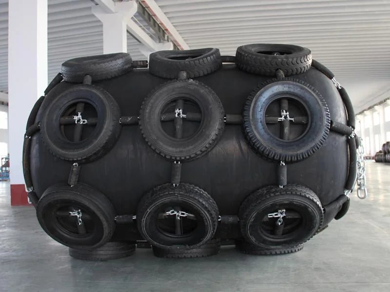
JettyGuard supplies pneumatic fenders across the full OCIMF size range — from 1.0×2.0 m for small vessel STS to 4.5×9.0 m for VLCC lightering operations.
All fenders are manufactured to ISO 17357-1:2014 with type test reports available. Standard initial pressure is 50 kPa, matching the OCIMF design basis directly.
We supply both mold-type and wrapped-type construction. For STS operations with high frequency — more than two operations per month — mold-type fenders offer more consistent wall thickness and longer service life. For lower-frequency operations or budget-constrained projects, wrapped-type fenders meet the same ISO 17357 performance requirements at a lower price point.
Need ship-to-ship transfer fenders sized to OCIMF requirements? Send us your vessel displacement data and operation type. We will confirm the fender size, quantity, and provide a quotation with ISO 17357 test documentation.
Frequently Asked Questions
What is the minimum number of fenders required for STS operations?
It depends on the equivalent displacement coefficient (C) and is non-monotonic, not a simple sliding scale: 3+ for C up to 10,000; 4+ for C from 30,000 to 100,000; 5+ at C=150,000 and C=200,000; but back down to 4+ at C=330,000 and C=500,000. Always read the exact row in OCIMF Table 9.1 for the calculated coefficient rather than assuming quantity rises steadily with vessel size. These are OCIMF minimums — operators may add secondary bow and stern fenders for roll protection in swell conditions.
Can foam fenders be used for STS transfer instead of pneumatic?
No. The OCIMF STS Transfer Guide specifies pneumatic fenders. Foam fenders have different force-deflection characteristics and cannot conform to two moving hulls the way a pneumatic fender does. The hull contact pressure distribution from a rigid foam fender exceeds safe limits for ship-to-ship contact.
What initial pressure should pneumatic fenders have for STS?
50 kPa (Pneumatic 50) is the OCIMF standard. The selection tables, energy absorption values, and reaction force data in the Guide are all based on 50 kPa initial pressure. Using 80 kPa changes the performance envelope and does not align with the Guide’s design basis.
How do I calculate the equivalent displacement coefficient for STS?
Use the formula: C = (2 × W_A × W_B) / (W_A + W_B), where W_A and W_B are the displacements of the two vessels in tonnes. If C falls between two values in the OCIMF selection table, select the fender size for the higher coefficient.
Does OCIMF require ISO 17357 certification for STS fenders?
The OCIMF Guide does not explicitly mandate ISO 17357 by name, but it specifies performance parameters (energy absorption, reaction force, deflection) that align with ISO 17357 test methods. In practice, terminal operators and P&I clubs require ISO 17357 compliance as proof that the fender meets the performance assumptions in the Guide.
Specifying fenders for an STS project? Share your vessel classes and operation type — we will confirm the OCIMF-compliant size, quantity, and provide full fender selection for LNG terminals engineering support.