

Most procurement specs reference “ISO 17357” without specifying which part, which fender type, or which inspection clauses apply. The result: ambiguity that leads to mismatched expectations between buyer and manufacturer.
ISO 17357 is the international standard for floating pneumatic rubber fenders, published in two parts. Part 1 (ISO 17357-1:2014) governs high-pressure fenders at 50 kPa or 80 kPa initial inflation pressure. Part 2 (ISO 17357-2:2014) governs low-pressure fenders at 7 kPa. Both replaced the single-document ISO 17357:2002.

What ISO 17357 Actually Covers
The original ISO 17357:2002 was a single document covering only high-pressure pneumatic fenders. In 2014, ISO split it into two parts to also address low-pressure fenders manufactured from coated textile rather than reinforced rubber.
| Attribute | ISO 17357-1:2014 (Part 1) | ISO 17357-2:2014 (Part 2) |
|---|---|---|
| Fender type | High-pressure pneumatic | Low-pressure pneumatic |
| Initial inflation pressure | 50 kPa or 80 kPa | 7 kPa |
| Construction material | Synthetic-tyre-cord reinforced rubber | Vulcanized-rubber-coated textile |
| Fender types defined | Type I (net-type), Type II (sling-type) | Clamped end, moulded end |
| Typical application | LNG terminals, STS transfer, offshore SPM | Harbour berthing, smaller vessels |
| Performance test deflection | 60 ± 5% | 60 ± 5% |
The distinction is pressure-based, not manufacturing-method-based. Both mould-type and wrapped-type high-pressure fenders fall under Part 1. Part 2 covers a fundamentally different product category.
This article focuses on Part 1 — the standard governing fenders used in LNG, FSRU, and ship-to-ship transfer fender applications.
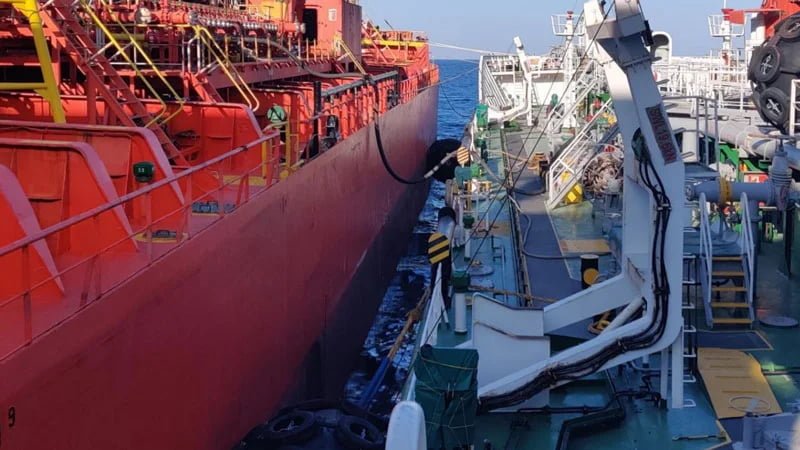
High-Pressure Fender Types Under ISO 17357-1
ISO 17357-1:2014 Clause 4.1 defines three construction types:
-
Type I (Net-type) — Fender body covered by a chain net, wire net, or fibre net. Usually fitted with used tyres or rubber sleeves for additional protection. The bead ring and cord turn-up construction at the flange can be excluded for this type (Clause 6.1.6).
-
Type I Single — Net-type with a flange opening at only one end. The other end has no metal parts, allowing safe deformation under over-compression. Installed with the no-metal end facing the expected impact zone.
-
Type II (Sling-type) — No protection net. Each end has a lifting device connected with a guy-chain or guy-rope. The fender body itself is the contact surface.
Clause 4.2 defines two pressure ratings:
| Rating | Initial internal pressure | Typical application |
|---|---|---|
| Pneumatic 50 | 50 kPa | Standard — most STS and terminal operations |
| Pneumatic 80 | 80 kPa | Higher energy absorption per unit size — confined berths, larger vessels |
Pneumatic 80 fenders absorb roughly 40% more energy than Pneumatic 50 fenders of the same diameter and length, but generate proportionally higher reaction force.
Fender sizes range from 500 × 1,000 mm to 4,500 × 12,000 mm (diameter × length) in the standard’s performance tables. Custom sizes are permitted under Clause 6.3.3, provided they satisfy the pressure requirements of the next-larger-diameter standard size.
Safety valves are mandatory for fenders ≥2,500 mm diameter (Clause 6.1.7). Smaller fenders can be equipped with one on request.
Performance Requirements: Energy Absorption and Reaction Force
Fender performance under ISO 17357-1:2014 is defined by three parameters at rated deflection:
-
Guaranteed Energy Absorption (GEA) — The energy the fender absorbs without permanent deformation or failure. Rated at 60 ± 5% deflection (Clause 7.3.3).
-
Reaction Force (RF) — The force transmitted to the vessel hull at GEA deflection. Tolerance: ±10% (Clause 7.3.4).
-
Hull Pressure — Internal air pressure at GEA deflection, equal to the pressure applied to the vessel hull contact area.
| Parameter | Requirement | Reference |
|---|---|---|
| GEA deflection | 60 ± 5% | Clause 7.3.3 |
| RF tolerance | ±10% of rated value | Clause 7.3.4 |
| GEA pass criterion | Achieve 100% GEA without exceeding 65% deflection and 110% RF | Clause 8.2.1 |
| Compression recovery | >97% of original diameter within 5 min | Clause 8.5.2 |
For example, an ISO 17357-1:2014 Pneumatic 50 fender sized 3,300 × 6,500 mm has a rated GEA of 1,814 kJ and rated RF of 3,015 kN. The delivered fender must absorb at least 1,814 kJ at no more than 65% deflection, with measured RF between 2,714 kN and 3,317 kN.
These values connect directly to pneumatic fender selection for LNG terminals — the designer calculates berthing energy, then selects a fender size whose GEA exceeds that energy with an appropriate safety factor.
Material and Construction Requirements
Rubber Compounds (Table 3)
| Property | Test method | Outer rubber | Inner rubber |
|---|---|---|---|
| Tensile strength | ISO 37 | ≥18 MPa | ≥10 MPa |
| Elongation at break | ISO 37 | ≥400% | ≥400% |
| Hardness (Shore A) | ISO 7619-1 | 60 ± 10 | 50 ± 10 |
| Tear strength | ISO 34-1 | ≥400 N/cm | No requirement |
| Compression set (70°C, 22h) | ISO 815-1 | ≤30% | No requirement |
| Ozone resistance | ISO 1431-1 | No cracks (20% elongation, 50 pphm, 40°C, 96h) | No requirement |
| After aging (70°C, 96h) | ISO 188 | Tensile/elongation ≥80% of original; hardness change ≤8 | Same |
Reinforcement: Tyre Cord vs Canvas
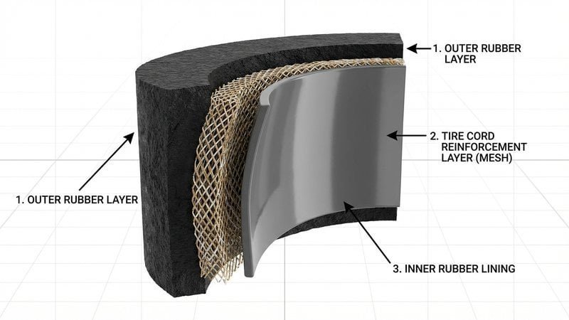
ISO 17357-1:2014 specifies synthetic-tyre-cord layers for reinforcement (Clause 6.1.1). Annex A explains why: tyre cord has strength in one direction (warp), with minimal weft threads. This eliminates friction and wear between cord threads during compression cycles.
Canvas fabric (belt fabric or tyre-cord chafer) has strength in both warp and weft directions, creating friction points at every intersection. Annex A explicitly states that canvas fabric “shall not be used for the high pressure pneumatic floating fender.”
Bead Ring and Flange
The bead ring diameter must be less than 0.20D (Clause 6.1.6), where D is the fender diameter. This keeps metal parts safe from permanent deformation during over-compression near 80%. For Type I (net-type) fenders, the bead ring and turn-up construction can be excluded.
Testing and Inspection: What ISO 17357 Actually Requires
ISO 17357-1:2014 defines a three-tier testing and inspection framework:
Clause 8 — Prototype Fender Test
A full-scale performance test required once per fender design. Covers:
- Performance test (Clause 8.2) — Parallel compression at ≤80 mm/min until GEA is reached. Two repetitions, 5-min interval. Results are the mean of both tests.
- Angular compression test (Clause 8.3) — Determines deformation properties under angled loading.
- Durability test (Clause 8.4) — Minimum 3,000 repetitive compression cycles. No cracks or harmful defects permitted. No GEA reduction accepted.
- Compression-recovery test (Clause 8.5) — After GEA compression held for 1 min, diameter must recover >97% within 5 min.
- Puncture-resistance test (Clause 8.6) — CBR test per ISO 12236. Breakthrough force must exceed 15 kN.
Prototype test certificates are valid for 10 years. The certificate must be evaluated by a major classification society. Fenders smaller than the prototype (same design and construction, fewer plies) do not require a separate prototype test.
Clause 9 — Commercial Fender Test
Acceptance testing for every production order:
| Test | Scope | Frequency |
|---|---|---|
| Rubber material test (Table 3, item 1) | Hardness | Every production lot |
| Rubber material test (items 2–5) | Tensile, elongation, tear, compression set, ozone | Once per year |
| Dimensional inspection | Diameter and length at initial pressure | Every fender |
| Air-leakage test | 30 min at initial pressure, no leakage | Every fender |
| Hydrostatic-pressure test | 10 min at rated test pressure, no leakage | 1 per 20 fenders |
Dimensional tolerances: length +10%/−5%, diameter +10%/−5% (Clause 9.3).
Clause 12 — Third-Party Independent Inspection
The buyer can request independent inspection by a major classification society (BV, DNV, ABS, Lloyd’s Register, or equivalent). This covers:
- Confirmation of tyre cord material certificate
- Evaluation of rubber material test results
- Evaluation of dimensional inspection results
- Evaluation of air-leakage test results
- Witness and confirmation of hydrostatic-pressure test
- Witness and confirmation of marking
Clause 12 is optional — it applies only when the buyer’s specification requires it. For LNG terminals, FSRU projects, and operations governed by OCIMF STS fender requirements, third-party inspection is standard practice.
How to Write an ISO 17357-Compliant Procurement Spec
Clause 5.1 lists what the buyer must state in a purchase order or inquiry:
- Standard number and year: ISO 17357-1:2014
- Fender size: diameter × length (from Table 1 or Table 2, or custom per Clause 6.3.3)
- Fender type: Type I, Type I Single, or Type II
- Initial internal pressure: 50 kPa or 80 kPa
- Fender colour (default: black)
- Safety valve requirement (if fender <2,500 mm and valve is needed)
- Identification system requirement (embedded serial number)
- Third-party inspection requirement (Clause 12)
A practical procurement clause reads:
“Fenders shall comply with ISO 17357-1:2014. Size: 3,300 × 6,500 mm, Type II (sling-type), Pneumatic 50. Third-party inspection per Clause 12 is required; inspection authority: Bureau Veritas. Manufacturer shall provide prototype test certificate per Clause 8, commercial test reports per Clause 9, and material certificates for synthetic tyre cord.”
Specifying Clause 12 explicitly removes ambiguity. Without it, the manufacturer is only obligated to perform Clause 9 batch testing — which does not include independent verification of performance data.
For Yokohama-type pneumatic fenders used in LNG and STS operations, always specify Type I or Type II construction, the pressure rating, and Clause 12 inspection. “Yokohama” is a brand name — the governing standard is ISO 17357-1:2014.
Frequently Asked Questions
What is the difference between ISO 17357 Part 1 and Part 2?
Part 1 (ISO 17357-1:2014) covers high-pressure pneumatic fenders inflated to 50 kPa or 80 kPa, made from synthetic-tyre-cord reinforced rubber. Part 2 (ISO 17357-2:2014) covers low-pressure fenders inflated to 7 kPa, made from coated textile. They are different product categories with different construction, materials, and applications.
What is the difference between Type I and Type II under ISO 17357-1?
Type I uses a protection net (chain, wire, or fibre) over the fender body, usually with tyres or rubber sleeves. Type II has no net — it uses slings and a lifting device at each end. Both must meet the same performance requirements. Type I is more common for STS and LNG; Type II is used where net abrasion or entanglement is a concern.
Does ISO 17357 require third-party inspection?
Not automatically. Clause 12 defines the framework for third-party inspection by a classification society (BV, DNV, ABS, LR), but it only applies when the buyer’s specification requires it. For LNG terminals and FSRU projects, buyers almost always require Clause 12 inspection.
How long is a prototype test certificate valid?
Ten years from the test date (Clause 8.1). After ten years, the manufacturer must repeat the prototype fender test. The certificate must be evaluated by a major classification society.
Need ISO 17357-1:2014 compliant pneumatic fenders for your project? Send JettyGuard your vessel class and berthing energy requirements — we confirm the correct fender specification during engineering review.